BEANS REELS ![]()
Bean Copter Micro FPV platform workshop

01
02
03
04
05
06
07
08
09
10
01![]()
> > > > > > > > Part one - What is a drone?
WHAT IS A MULTICOPTER AND WHAT IS A DRONE ?
A multicopter is a mechanically simple aerial vehicle whose motion is controlled by speeding or slowing multiple downward thrusting motor/propeller units.
An unmanned aerial vehicle (UAV), commonly known as a drone, as an unmanned aircraft system (UAS), and also referred by several other names, is an aircraft without a human pilot aboard. The flight of UAVs may be controlled with various kinds of autonomy : either by a given degree of remote control from an operator, located on the ground or in another vehicle, or fully autonomously, by onboard computers
In the image we can see on the left a REAPER MILITARY UAV that is a "drone" due to his autonomous capabilities.
On the right is commercial DJI Phantom that is also a "drone" but also can be controlled in manual mode.
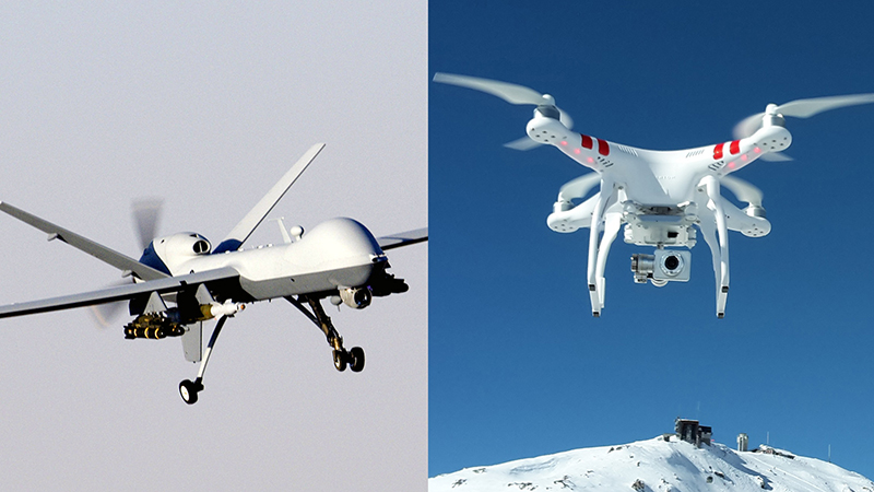
The term "drone" is lazy and inexact.
The fundamental difference between the terms “drone” and “quadcopter” is one of characterization – drone is the general term used for all unmanned aerial vehicles, though quadcopter identifies with a particular set of drones with four engines that make lift for vertical takeoff through their propellers
1. It isn't wrong to call almost any kind of remotely or self-directed vehicle a "drone."
2. All unmanned aircraft may be considered "drones."
3. It's basically impossible to come up with a currently flying example of a quadcopter that isn't an unmanned aircraft (part of an "unmanned aircraft system") and therefore, at the end of the day... a drone.
Quadcopter is drone, it’s a fact. Pretty much like bacon is pork or maybe...a cow ?
What is the difference between a multicopter and a a drone ?
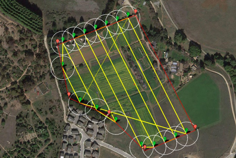
A multicopter becomes a UAV or Drone when it is capable of autonomous flight. Normally this means taking the accelerometer and gyro information and combining it with barometer and GPS data so the flight controller understands not only it’s orientation but also it’s position.
What does it means ? We can program it to go somewhere autonomously do something and return home.
There is a video examplo of a "drone" multicopter wich can switch between "manual mode " and "autonomous mode".
02![]()
> > > > > > > > Part two - What is FPV?
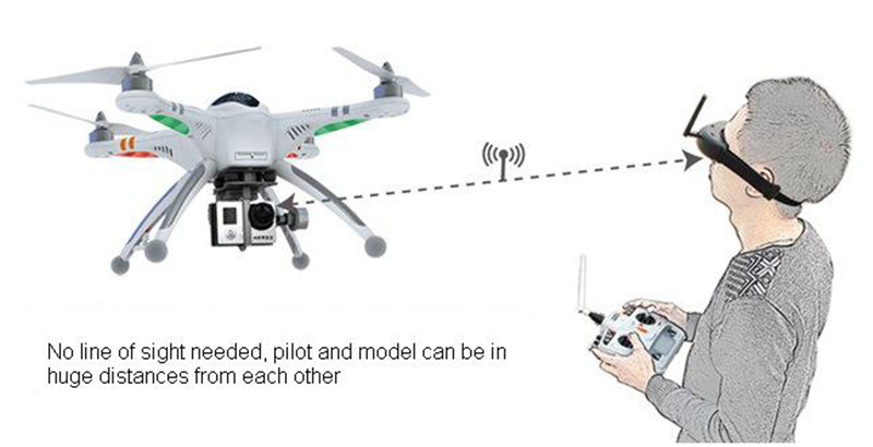
Usually we fly RC models in parks, or fields, but generally we fly by watching the model flying while controlling it on the ground.
The main thing is, we always look at the model, check its position and control it accordingly.
This is what we call LOS (line of sight) flying.
FPV (which stands for First Person View) in its simplest form regards adding a small video camera and video transmitter to your model. Then, with a video receiver and a video display (video goggles, a video monitor, or both), the pilot/copilot can view the image from the model in real time, which gives the effect of "being in the cockpit."
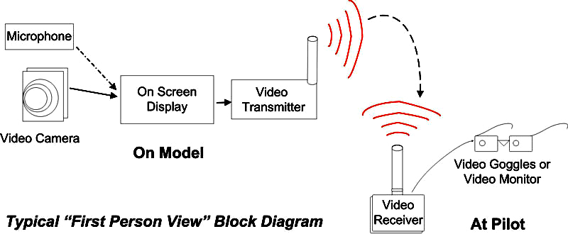
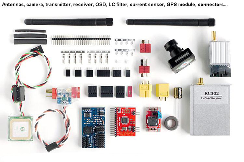
Main components (FPV gear)
- video transmitter (vtx) + antenna (air)
- micro camera (air)
- video receiver (vrx) + antenna (gnd)
- ground display unit (tv, lcd monitor, laptop display, video goggles, …)
Extended components (improvements)
- low-pass” filter (filters the unwanted frequencies, that can influence the RC link) (air)
- LC filter (filters the current fluctuations that can affect the picture quality) (air)
-ground station (integration of the vrx, monitor, video recorder and more to one unit, usually a suitcase) usually mounted on a tripod
- diversity receiver (handles input from more antennas, selects the best signal) (gnd)
- antenna tracker system (turns the receiver antenna towards the model automated)
- DVR (“digital video recorder” – records the picture coming from the vrx) (gnd)
- power bank for the groundstation (gnd)
- OSD, video information about position,orientation, altitute,etc embeded on the video image (air)
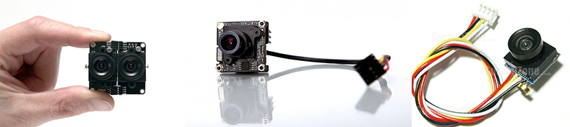
COMPONENTS ONE BY ONE: CAMERA
One of the most important components in FPV flying is the fpv camera. If the camera is not good enough for the purpose, it has effect on the whole flight. Be carefull while choose the voltage range they admit is usually small.
CCD vs CMOS
The advantage of the CCD sensors over CMOS is that there is no “rolling shutter” effect on CCD cameras. On the other side, the CMOS cameras have higher resolutions, thus, nice picture.
> > Note that the maximum horizontal lines that the analog transmitter can transmit is 576
VIDEO STANDART
There are two major types of video standards that we use FPV cameras: PAL and NTSC. While the former has slightly bigger resolution, the latter has slightly slower frame rate ( that means the image get refreshed faster, very important during fast flying)
RESOLUTION
Camera resolutions are specified as TVL (TV lines) and go from 480 up to 1000. Usually, the higher the TVL value, the better the picture, even if the maximum analog transfer rate is of 576 tv lines, the superior quality built and lens, make the higher specs camera have a better final image with more focus,detail,color rate and fast change between dark/light areas.
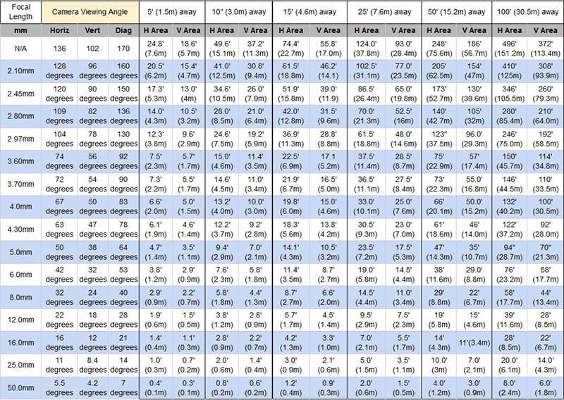
F.O.V / CAMERA LENS
The FOV or camera angle gives us information how much angle the camera sees. The values are given in “mm” which equals to the focal length. The lesser the number, the wider the angle. The cameras that are generally used in FPV has 2.8mm lens that gives us around 90 degree angle horizontal and 80 degree angle vertical. By using a 3.6mm lens this decreases to 75/65 degrees. The more narrow the angle, the more details we see on the picture
As a good start point for beginners is to use a wide angle camera as it allows to see lot of things, but a cons it is more difficult to calculate distances
.
NIGHT VISION
For night flying we use cameras that have very low LUX ratings. A camera below 0.001 LUX can see nearly perfectly in the dark night.A nice camera in this family is fpv OWL micro camera (the image in this kind of camera is bitone due to what the camera sees is infrared emitance)
COMPONENTS ONE BY ONE: ANTENNA
The antenna is the essential component of every FPV system. When we say “essential” we mean it. A wrong antenna can degrade the range of the system to very low values, making flying impossible.
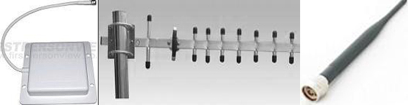
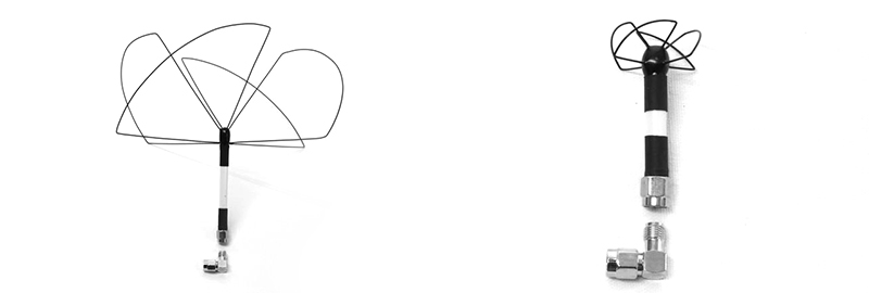
Linear are now considered by most as old school technology for FPV with the realization of circular polarization, but it still has its place for small micro aplications.
Main attributes are:
> > >polarization ( vertical, horizontal, circular)
This depicts how you mount an antenna to match the waveforms from transmitter to receiver. An omin antenna has a linear polarized waveform so when mounted upright the waveforms are transmitted vertically. The receivers antennas polarization must then match to receive a polarized signal
> > > directivity (omni, directional)
> > >SWR standing wave ratio
When a receiver is connected to an antenna the impedance of the antenna and feed line must match as close as possible for most efficient reception
> > >"gain" directivity
The two antenna characteristics, among others, that impact link performance to a large degree are directivity and polarization.A simple dipole antenna has a gain of 2.15 dbi and has a directivity pattern, in free space, shaped like a torus or donut.his can be an advantage in some circumstances but in RC systems, that “ hole in the middle” can be a real problem
THIS IS WHY YOU SHOULD NEVER POINT THE ANTENNA AT YOUR MODEL.

> > > bandwidth (wich band are they designed for)
An antenna designed for a specific frequency has certain characteristics at that frequency only. As the frequency is changed, plus or minus, from this center frequency, those characteristics will change to some degree
For radio systems that operate on a single frequency, bandwidth isn’t much of an issue. However, a number (if not most) of 2.4 GHz systems use spread spectrum or frequency hopping technology, which require operation over a range of frequencies. For these systems, bandwidth is significant.
Most wifi,bluetooth,rc transmitters use the 2.4 ghz bandwitdh so it is a very noise band. To get best picture quality most of people use the 5.8ghz band that gives less penetration rate but better qualitity and it is much less busy.
Most used frecuencies are
- 900mhz where the signal go easy around and penetrate walls and trees
-1.2 ghz( 1200mhz) nice penetration but antennas are big,be carefull to stay away for GPS and airplane navigation frecuencies(1227.60 1575.42, 962-1213 mhz)
-2.4ghz (used for long range fpv but you have to use another band transmitter),very crowded frecuency,much more antennas to choose
-5.8ghz, perfect for short range,easy to setup,works with 2.4ghz transmitter, very small antennas.
Here you can see the comparison in size between a 1.2ghz and 5.8 ghz antenna.
> > > material / size/ weight
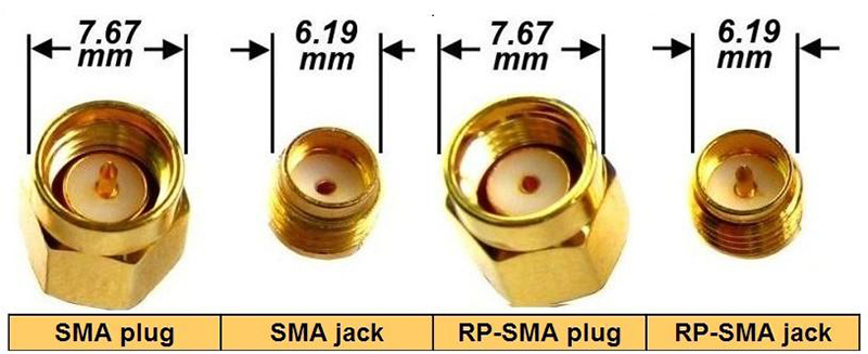
> > > connector type SMA vs RP-SMA (male vs female)
COMPONENTS ONE BY ONE: vTX,vRX)
The video transmitter is the device that transmits an analog (some digital devices exists already) signal of the fpv video camera to the ground, where a video receiver catches the signal and processes it. The signal is transmitted in SD quality, that means 576 horizontal lines.
ATTRIBUTES OF vTX
-frecuency/band
-RF power
-input voltage
-antenna connector
-size weight
ATTRIBUTES OF vRX
-frecuency/band
-sensitivity
-noise filtering
-build (modular/cased)
-diversity
-number of AV out connectors
There are some more sophisticated solutions where one needs precise and stable control all the time. In these cases, a technology called “diversity” is used. It can be achieved either by multiplying the receiver modules (static), or by using an antenna tracker module (dynamic), that is able to track the multicopter in the air and automatically position the antenna to get the best signal.
Displays vs Googles
LCD > > > > > > > > > > > > > > > > > > > > > > > > > > > > > > > > > > > GOOGLES
-reflections on sunny days > > > > > > > > > > > > > > > > > > > > > > > >no reflections
-display brightness > > > > > > > > > > > > > > > > > > > > > > > > > > > > optical incompatibility
-more resolution > > > > > > > > > > > > > > > > > > > > > > > > > > > > > discomfort in view
-powering > > > > > > > > > > > > > > > > > > > > > > > > > > > > > > > > powering
-large displays > > > > > > > > > > > > > > > > > > > > > > > > > > > > > > small displays
-cabling > > > > > > > > > > > > > > > > > > > > > > > > > > > > > > > > >no cabling
Of course, loosing the picture in many cases means loosing the control and crash.
How to get the maximum range
Generally, the lower the frequency, the better is the penetration (possibility for the signal to get through). Of course again, by using high gain directional antenna, more sensitive receiver or higher RF output power will help making the penetration better.
General rule of thumb is ALWAYS to increase the antenna gain/vRX sensitivity, and AVOID increasing the vTX RF power. The reason is simple, the high RF power levels can simply affect other devices onboard, even the RX and this can lower the range for the RC link which we need to avoid.Also note that by increasing the vTX power it will get more and more hot, and as a result it can easily burn out.
A typical situation is when we use 2.4G for RC link (very widely used) and we need high penetration so we use 1.2/1.3G for video. In this case the vTX can (will) negatively affect the range of the RC link, that can get down even to 1/10 of its maximum range.
MAYDAY!! my video has bad quality
The video picture can generally be affected 2 ways, by EMI (electromagnetic interference, or RFI – radio frequency interference), coming from any onboard electronics device or by the unwanted voltage spikes, usually coming from the motors.
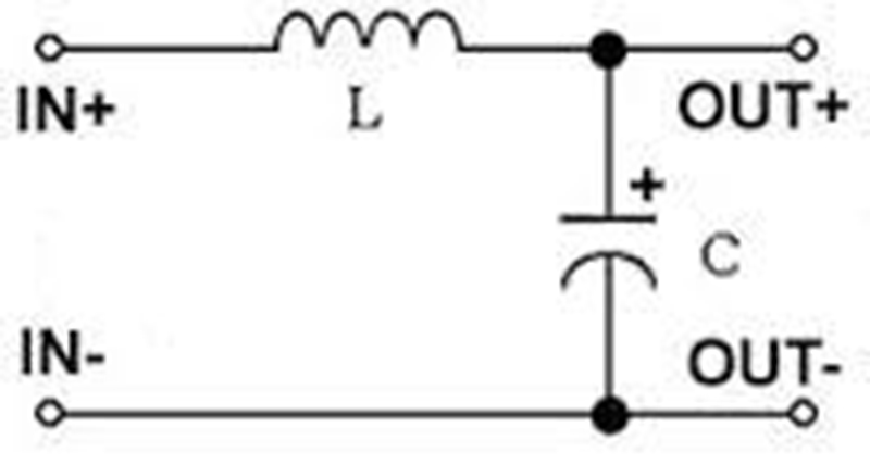
The latter can usually be cured (to a certain point) by using so-called “LC filters”. The “LC” comes from the names of the passive components used, capacitors and inductors. Making such a filter at home is relatively easy and very cheap, however, the result is not always satisfactory. A thumb of rule is to use as high capacitance and inductive components as possible.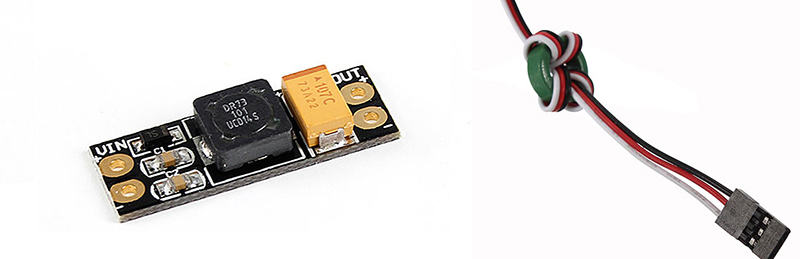
A good solution is to find the component that “makes the noise” and shield it as much as possible. The shielding can be done the easiest way by using some copper or aluminium foils for wrapping. In addition to this, we can use ferrite rings of different shapes and sizes, and twist the wires going to the transmitter around them as many times as possible. In many cases, just simply twisting the wires, going between the video components can be sufficient, to filter the noise.
about FPV legality and safety
Always obey the law when flying, and fly safely! Laws vary from locality to locality. Most video transmitters used for FPV flying require an amateur radio license to operate legally, depends mainly on wich frecuencies/power you use. FPV hobby frecuencies are 800-900mhz, 1.2ghz ,2,4ghz, 5,8 ghz
Common illegalities:
- illegal frequency usage, or transmitting on an allowed frecuency with not allowed power levels ( HAM license existence)
-accidentally powering the vTx on a frecuency that is already used by someone else, causing to blind him and crash.
-damage caused by unattendance or technical problems
-illegal usage of the airspace
-illegal usage of the flying area
The worst issue ever would be to fly close to airports or in forbidden airspace.
Most FPV video transmitters are broadband "analog" transmitters based on 1950's technology, with relatively limited range when compared to the range of your RC radio. One way to increase the range of the video link is to use a more powerful transmitter, but that uses more battery power.
Most commons power for FPV video transmitters are between 25mw (raceband) and 600mw.
Another way to improve range and video signal quality is to use two receivers on the ground, and to automatically select the one that has the stronger signal. This arrangement is called "diversity." Some ground stations provide diversity when two receivers are connected to them.
Youtube is filled with “how to fly a quadcopter” instructional videos, so that will be your starting point to figure out the basics. Once you get the basics you can do some amazing stuff like drone racing from point of view!
OSD on-screen display
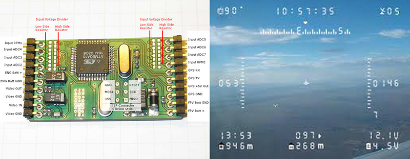
Is a small electronic component that gets installed between the fpv camera and the video transmitter. Its function is to display additional information, by overlaying it into the camera’s picture. These information are some essentials for flying, such as height, speed, heading, voltage, power consumed and many more.
The real power of the OSD shows up in a more sophisticated builds/projects, that use waypoint navigation and other automated advanced functions.
03![]()
> > > > > > > > Part three - How a drone flies
P-I-D correction algorithms
There are three parameters that a pilot can adjust to improve better quadcopter stability > > >P.I.D
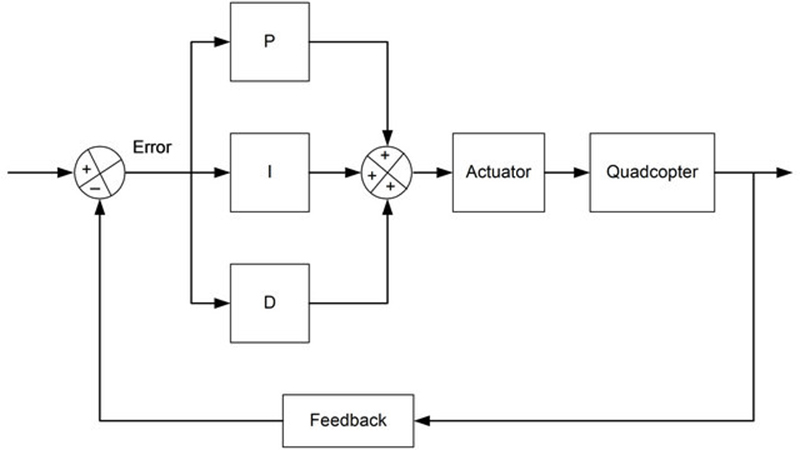
There are 3 algorithms in a PID controller, they are P, I, and D respectively. P depends on the present error, I on the accumulation of past errors, and D is a prediction of future errors, based on current rate of change. These controller algorithms are translated into software code lines.
ACROBATIC FLIGHT
- requires a slightly higher P
- requires a slightly lower I
- increase D
GENTLE SMOOTH FLIGHT
- requires a slightly lower P
- requires a slightly higher I
- decrease D
HERE YOU CAN SEE A VIDEO EXAMPLE OF DIFFERENT SETTINGS
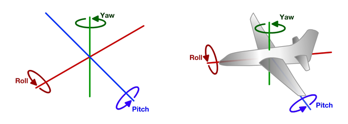
MOVEMENTS OF FLYING VEHICLES
TRANSMITTER MODES / HOW TO DRIVE THE VEHICLE
The remote control has some common main functions. For full autonomous operation at least six channels are required,with more you can assign more functions.
- Throlle > > > up/down in multicopters
- Yaw / Rudder > > > rotation on the Z axes
- Roll / Ailerons > > > rotation on the X axes
- Pitch / Elevator > > > rotation on the Y axes
- Mode switch1/2/.. > > > function assignation
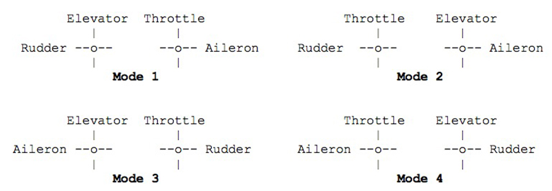
You'll see from the above 4 modes but few people fly anything other than Mode 1 or 2. There are also modes 5-8 where the elevator is reversed so the model goes up when you push the stick forward (yes, I have come across somebody who flew this way, he had no help when he started out and it made sense to him)
There is no right or wrong way to learn, the percentages of people flying on each mode varies in the UK and USA it is mainly mode 2, Europe and Australia mode 1.
Most people the world over fly mode 1 or 2, so which should you chose?
The technical answer is that for aircraft mode 1 is considered better as it separates the two main controls (aileron and elevator), which helps when flying precision aerobatics, also helps turning in racing multirotors as you mainly rotate with the rudder aka yaw, but there are many top competitive aerobatic pilots flying mode 2.
Mode 2 is considered easier to learn as you predominately use your right hand and most people are naturally right handed.
![]()
All the transmissions between the remote and the receiver come in a "coded" frecuency the normal outputs for Radiocontrol frecuencies are CPPM / PPM sum signal, S-BUS or Spektrum Satellite. They are mainly propietary brand modulations, so if you get a Spektrum you can only use spektrum products or modulation compatible one.
Most people are using 2.4GHz technology, but we can still encounter some “old” 35MHz and 72MHz systems.
We carefull wich one you buy the first time! Some are more expensives have more options than others.
More commons modulations are :
- Spektrum and DSM Compatible Receivers
MOTORS BASIC CONCEPTS
A multicopter is more efficient when it’s lighter, so you need to pick a good battery that has good capacity but light weight.Although you can choose the motors for the weight you want to carry, it’s always a good idea to carry as little weight as possible. Lightness is very important to all aircraft because any excess weight could reduce your battery life and maneuverability
A rule of thumb is Required Thrust per motor = ( Weight x 2 ) / 4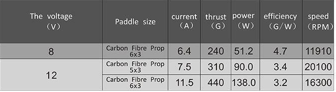
Brushed vs Brushless
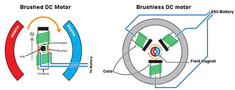
Advantage of brushed motors
-Inexpensive
-Simple wiring
-No need specialized ESC
Advantages of brushless
-Very low maintenance
-Higher speeds achievable
-Higher efficiency
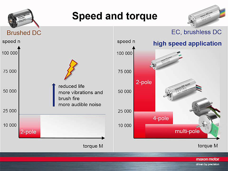
Motors used these days are almost exclusively of the “brushless” variety. That equates to minimal friction.A cylindrical shell of magnets rotates on precision bearings around a core of tightly and neatly coiled wire.
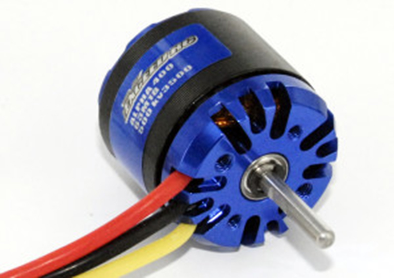
Battery and weight is not the only factor we need to consider when it comes to Efficiency, there is also motor efficiency. When choosing motors, apart from motor KV and thrust, we also need to look at Watt’s and efficiency.
MATCHING AN ESC TO YOU MOTOR (Electronic Speed Controller)
Now that we have confirmed that this motor is suitable for our application, we look at the Amp draw for our chosen motor/battery/propeller. In our case, this is maximum of 7.5A for a 5x3 prop, and 11.5A for a 6x3 prop. Since in our build we chose the 5x3 propellers, so we will need to use an ESC that is rated over 7.5A, so an 12A ESC would be a good choice for this motor/propeller running on a 3S battery.
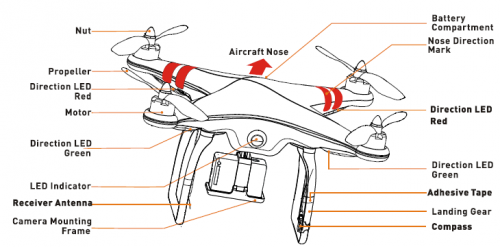
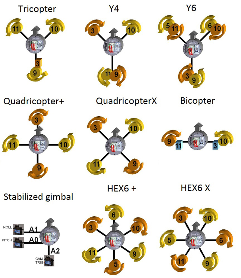
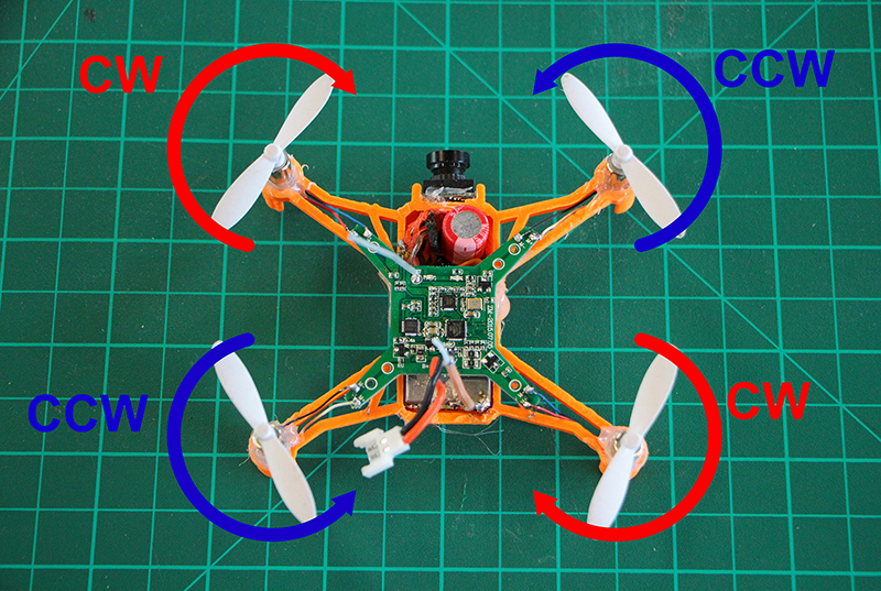
PROPELLERS AND ROTATION
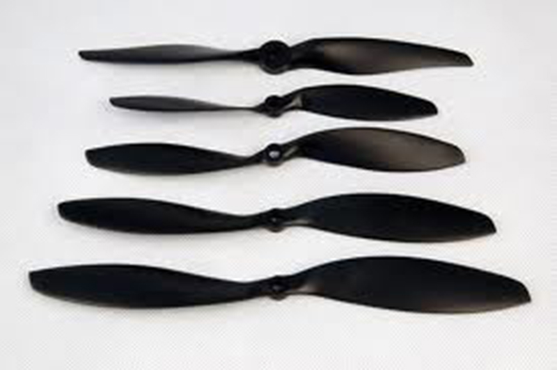
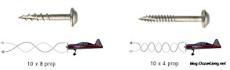
A quadcopter uses two clockwise(CW) and two counter-clockwise(CCW) propellers. Propellers are classified by length and pitch. For example 9×4.7 propellers are 9 inch long and has a pitch of 4.7.
Generally, increased propeller pitch and length will draw more current. Also the pitch can be defined as the travel distance of one single prop rotation. In a nutshell, higher pitch means slower rotation, but will increase your vehicle speed which also use more power
.
There are a few different types of propellers, such as plastic, carbon fibre etc.
A higher pitch propeller moves greater amount of air, which could create turbulence and cause the aircraft to wobble during hovering. If you notice this with your quadcopter, try to choosing a lower pitched propeller.
When it comes to the length, propeller efficiency is closely related to the contact area of a prop with air, so a small increase in prop length will increase the propeller efficiency. (pretty much like swimmers with larger hands and feet can swim faster, but also more tiring for them)
The orientation of the propeller depends mainly on your frame configuration.Each propeller needs an "opposite" so the torque that it produces is eliminated by another one.
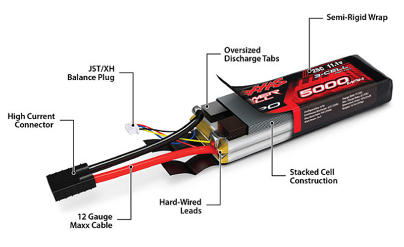
BATTERIES "hello LiPo"
LiPo batteries (short for Lithium Polymer) are a type of rechargeable battery that has taken the electric RC world by storm, especially for planes, helicopters, and multi-rotor. They are the main reason electric flight is now a very viable option over fuel powered models.
> > > LiPo batteries are light weight and can be made in almost any shape and size
> > > Rc LiPo have large capacities, meaning they hold lots of energy in a small package
> > > Rc LiPo have high discharge rates to power the most demanding electric motors
VOLTAGE
Unlike conventional NiCad or NiMH battery cells that have a nominal voltage of 1.2 volts per cell, LiPo battery cells have a nominal voltage of 3.7 volts per cell.
3.7 volt battery = 1 cell x 3.7 volts (1S)
7.4 volt battery = 2 cells x 3.7 volts (2S)
11.1 volt battery = 3 cells x 3.7 volts (3S)
14.8 volt battery = 4 cells x 3.7 volts (4S)
18.5 volt battery = 5 cells x 3.7 volts (5S)
22.2 volt battery = 6 cells x 3.7 volts (6S)
29.6 volt battery = 8 cells x 3.7 volts (8S)
37.0 volt battery = 10 cells x 3.7 volts (10S)
44.4 volt battery = 12 cells x 3.7 volts (12)
Unlike conventional NiCad or NiMH battery cells that have a nominal voltage of 1.2 volts per cell, LiPo battery cells have a nominal voltage of 3.7 volts per ceLL
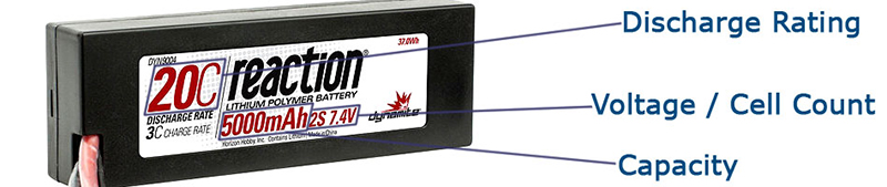
CAPACITY
Capacity indicates how much power the battery pack can hold and is indicated in miliamp hours (mAh). This is just a fancy way of saying how much load or drain (measured in milliamps) can be put on the battery for 1 hour at which time the battery will be fully discharged. 
The main thing to get out of this is if you want more flight time; increase the capacity of your battery pack. Unlike voltage, capacity can be changed around to give you more or less flight time.
DISCHARGE RATE
Discharge rate is simply how fast a battery can be discharged safely. Remember that ion exchange thing further up the page? Well the faster the ions can flow from anode to cathode in a battery will indicate the discharge rate. In the RC LiPo battery world it is called the “C” rating.
Most RC LiPo Battery packs will show the continuous C rating and usually a maximum burst C rating as well. A burst rating indicates the battery discharge rate for short bursts (a few seconds maximum) of extended power. An example might be something like "Discharge rate = 25C Continuous/50C Bursts".
04![]()
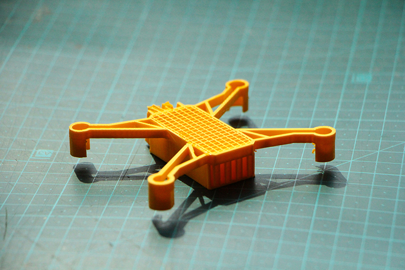
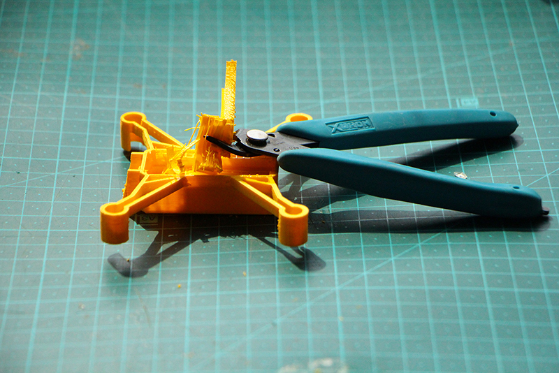
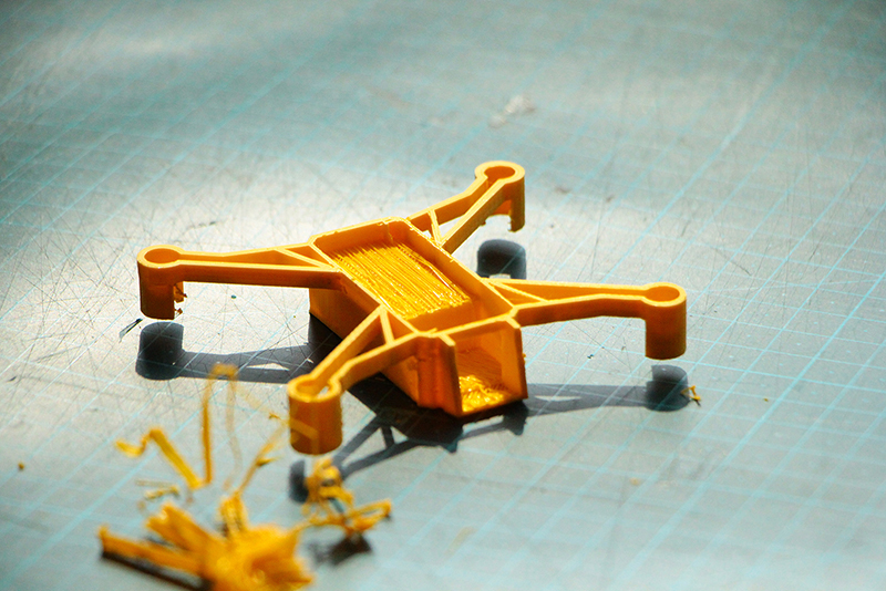
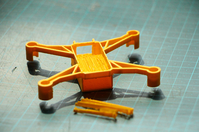
> > > > > > > > Part four - design the frame
05![]()
> > > > > > > > Part five - fpv-1 "video transmitter"
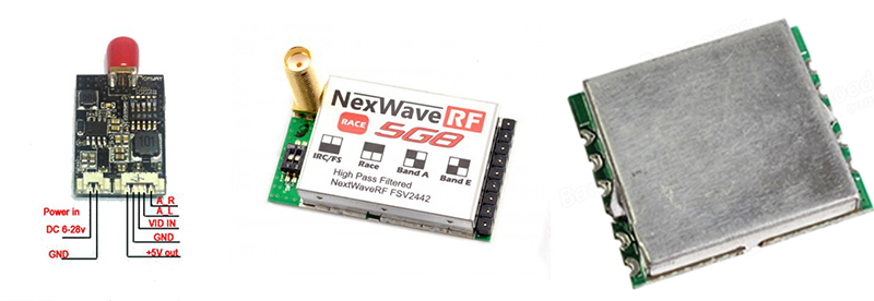
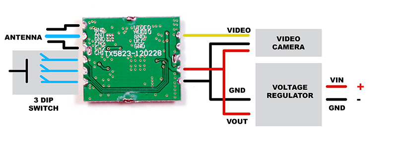
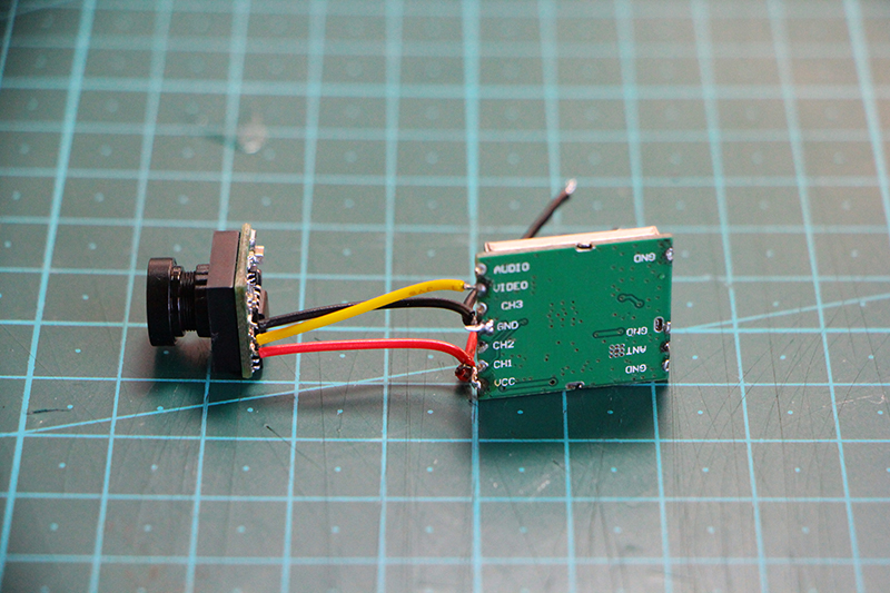
In this light weight micro FPV combo, we will be using the video transmitter TX5823, along with the nano FPV camera. This small 5.8Ghz video transmitter only weights 2.3g, but with amazing 200mW power. This schematic below is the connection diagram.
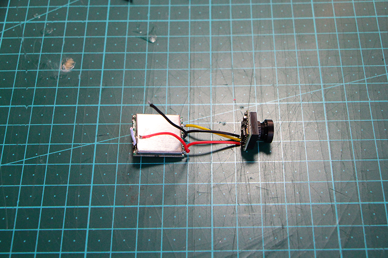
To get the best signal and keep away all the electronic noise of the motors is very important to use a clean power input for that you can use a LC filter, to keep the voltage controlled and the power consumption as minimum as possible we are going to power all the video equipment from a polulu voltage regulator with LC filter embeded.
With a circular polarized antenna, we can achieve more than 300 meters in range.If everything is correctly setup.
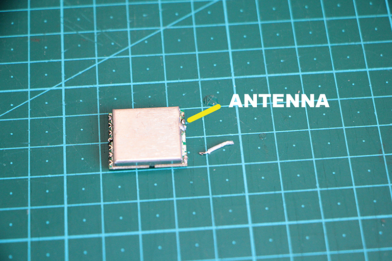
Linear polarized antenna can be made very small and light weight, especially useful for weight-critical application, such as on a micro quadcopter.
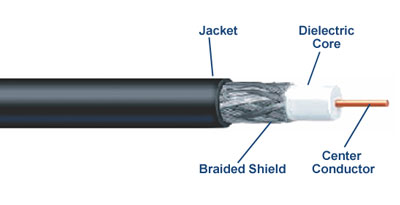
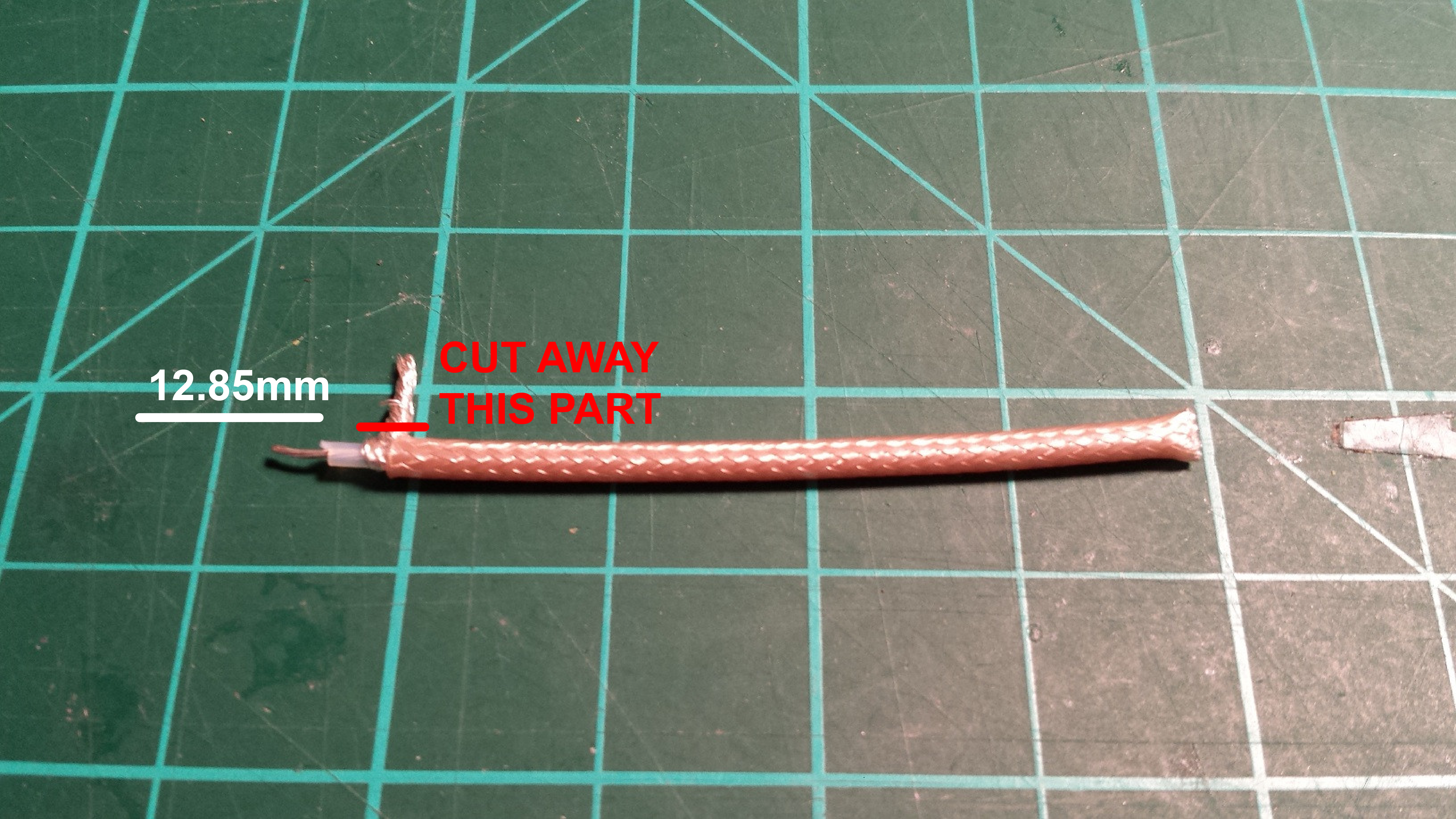
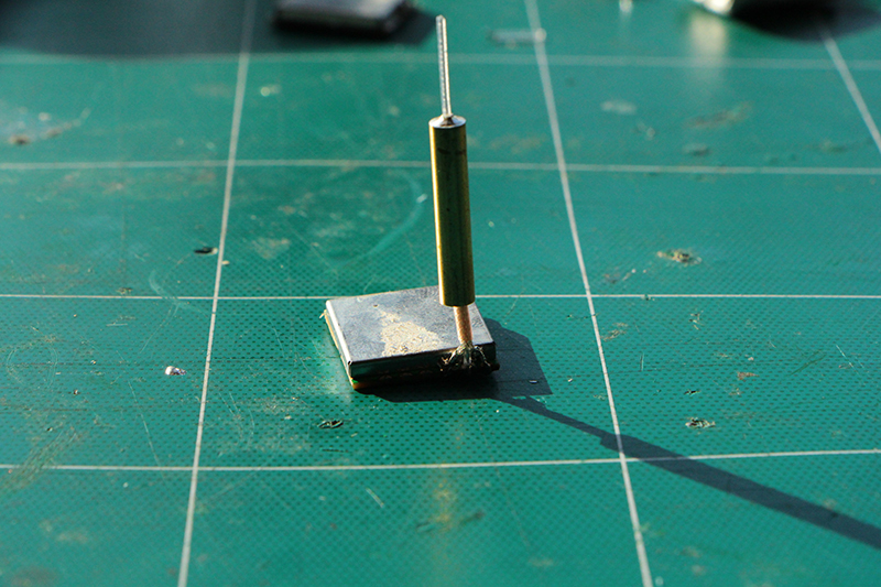
The more precise wire length is, the better signal you should get ideally. If you are using Coaxial Cable, it doesn’t matter how long the shell is, all that matter is the exposed wire (the part that is without the shielding)
In the pictures we use just a simple wire but to make the receiver part of the antenna being away as possible from the motor electromagnetic field we are going to use a RG316 Coaxial Cable.
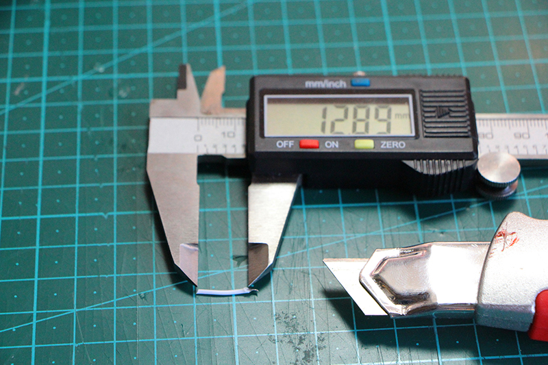
If the antenna is a quarter wave monopole antenna, then its length should be a quarter of the signal wavelength.We use 5.8ghz video transmission signal
If the wire is 12.92mm then it’s tuned for 5.8Ghz, but only a little shorter e.g. 12.70mm, and it’s now tuned to 5.9Ghz.
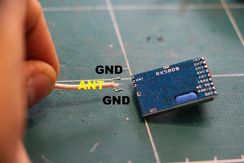
In the coaxial cable the "transmision wire" is protected from interference with another wire that works as shield.We have to solder this exterior shield to GND (ground)
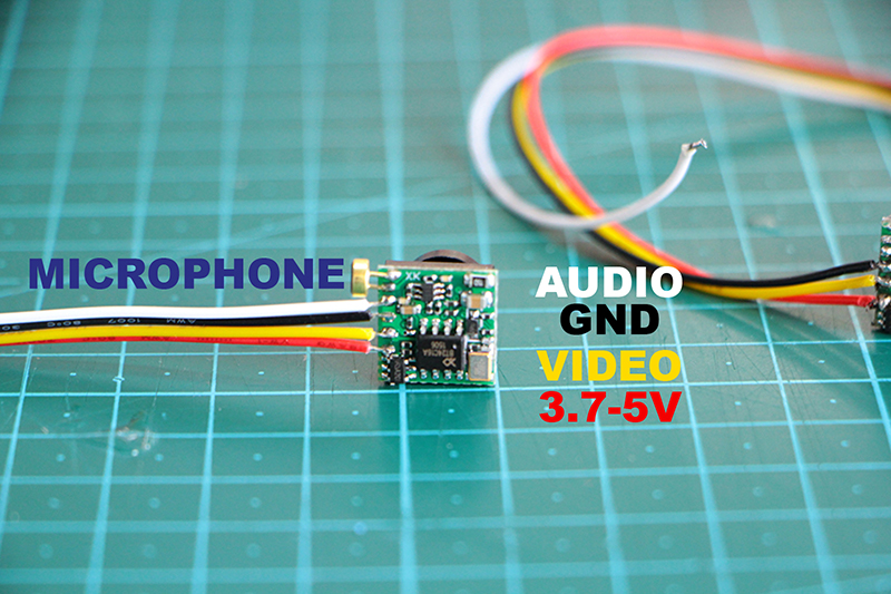
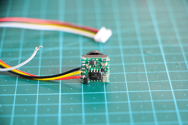
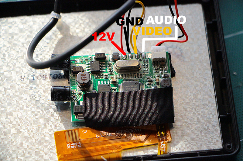
We will use a 600 TVL CMOS 170 degree wide angle camera.This micro camera operates or a voltage range or 3.7 to 5 V, so be carefull and measure the output power where you will connect it or you will "burn" the circuits.
It comes with an smal microphone that we are going to unsolder. The microphones in Fpv are almost useless as the only sound they capture is from the propellers.
The order of wires is
RED > POSITIVE
YELLOW > VIDEO SIGNAL
BLACK > NEGATIVE
WHITE > AUDIO SIGNAL
It comes with an smal microphone that we are going to unsolder. The microphones in Fpv are almost useless as the only sound they capture is from the propellers.
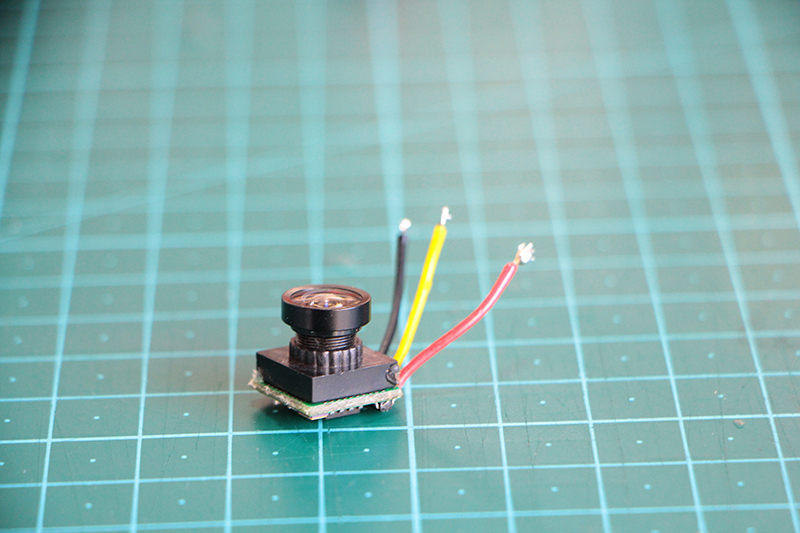
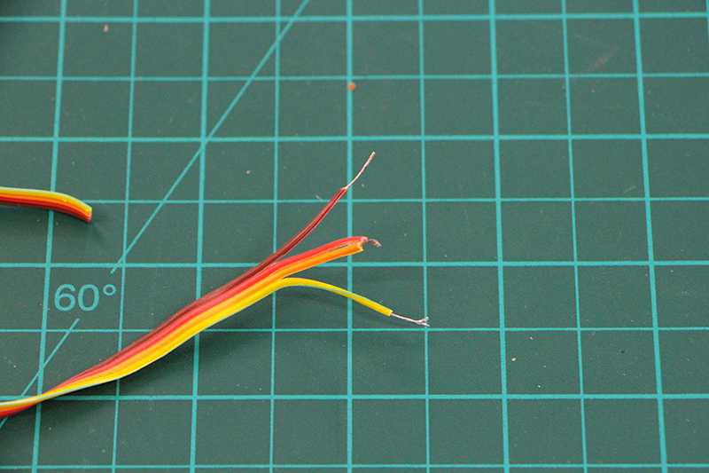
We unsolder the microphone and the white wire that it is AUDIO signal.
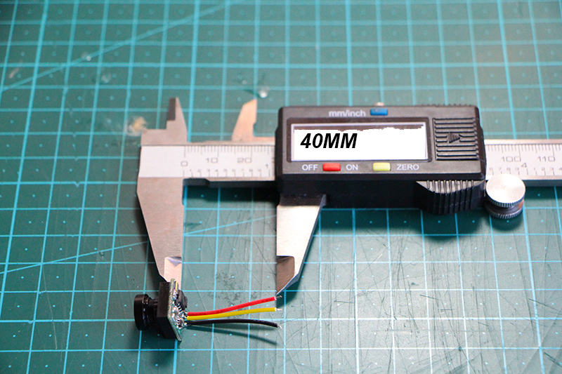
Cut all the wire more or less until you only have 27 mm less, this is for saving gram and not to have to much weight due to long wires we don't need but also to keep it easier to solder everything.
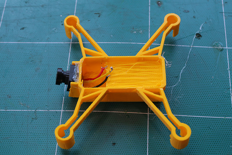
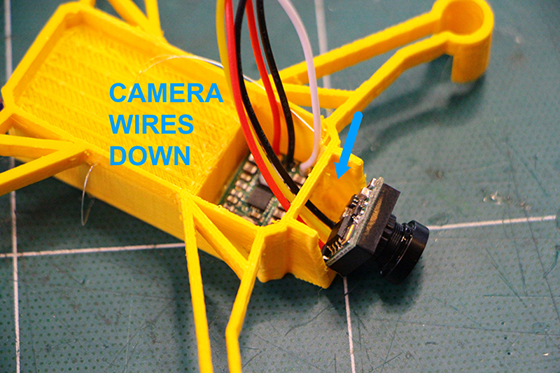
Remember to install the camera on the frame before soldering to the receiver. As the wire comes trought the front hole on the camera holder.
We can solder directly the connections to the receiver
 +
+
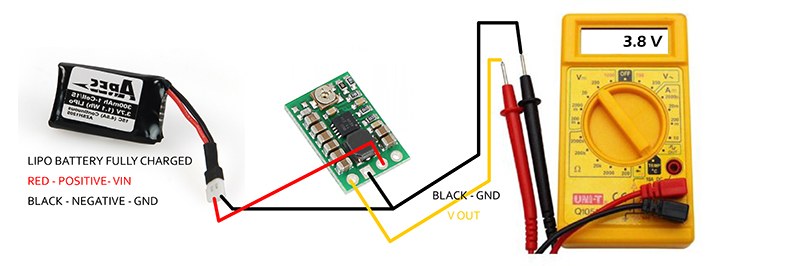
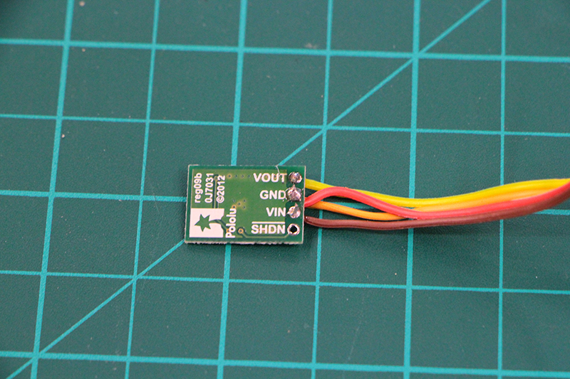
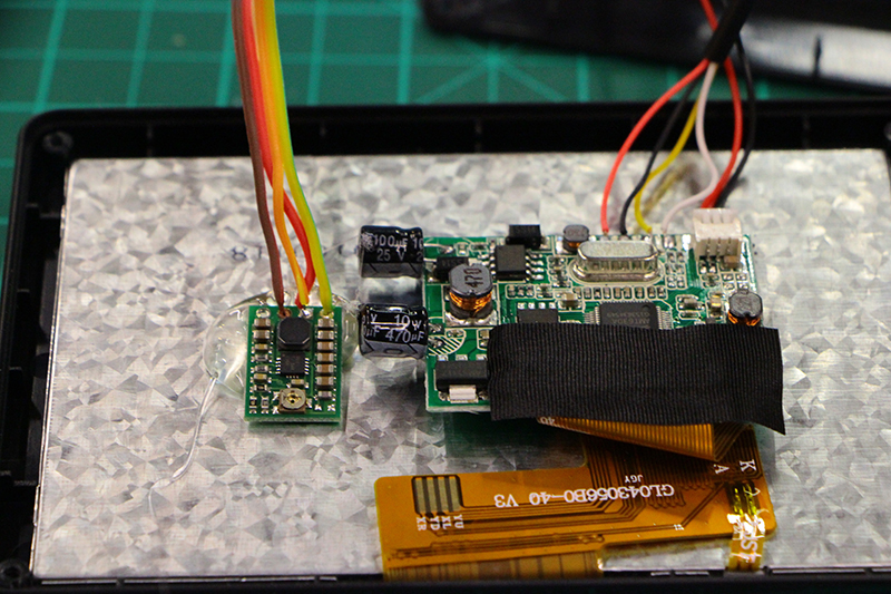
This is the polulu adjustable STEP-UP/STEP-DOWN voltage regulator S7V8A and Lc filter it will help us to have a constant and clean power for our FPV equipment.
The S7V8A switching step-up/step-down regulator efficiently produces an adjustable output between 2.5 V to 8 V from input voltages between 2.7 V and 11.8 V. Its ability to convert both higher and lower input voltages makes it useful for applications where the power supply voltage can vary greatly, as with batteries that start above but discharge below the regulated voltage. The compact (0.45″ × 0.65″) module has a typical efficiency of over 90% and can deliver 500 mA to 1 A across most combinations of input and output voltages.
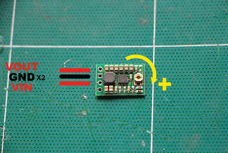
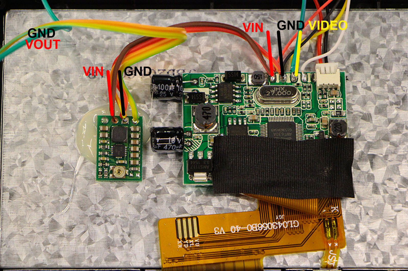
As we can see there is 4 connections but we will only use 3
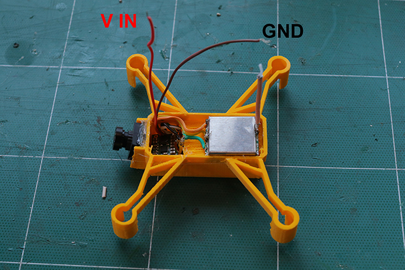
VIN > CONNECTED TO THE LIPO BATTERY
GND > COMMONG GND
VOUT > FOR POWERING THE TRANSMITTER AND CAMERA
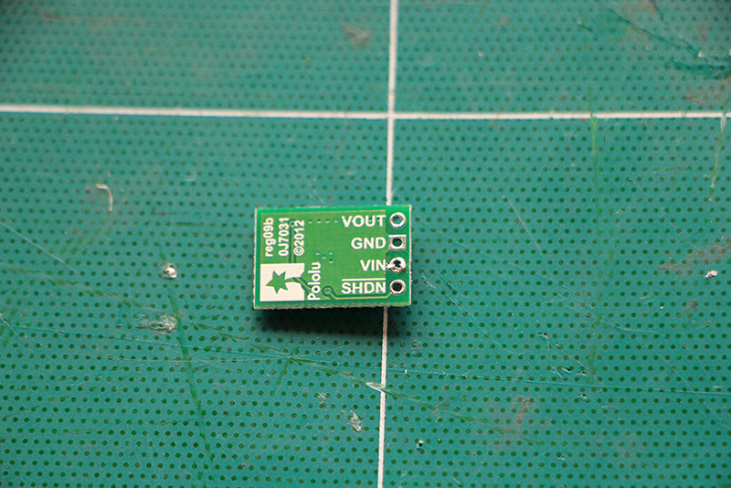
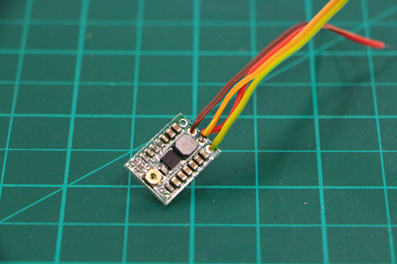
The output voltage can be measured using a multimeter. Turning the potentiometer clockwise increases the output voltage. The output voltage can be affected by a screwdriver touching the potentiometer, so the output measurement should be done with nothing touching the potentiometer.
The way to setup the ouput power is by turning the small screwwheel. If we turn clockwise we augment the voltage and if we turn underclockwise we turn it down.
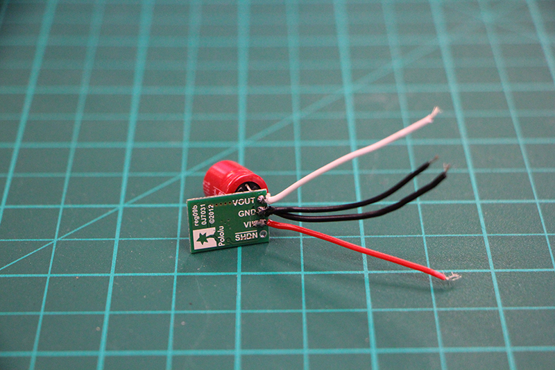
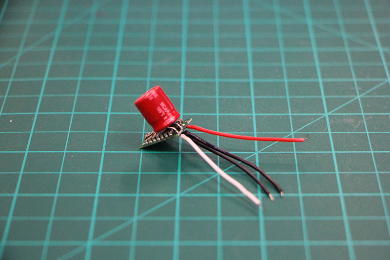
We proceed to solder FOUR connections to the regulator with caution not to make any short between the solders,wires or elements on the board.
We need to solder also one of the capacitor in the kit. Capacitors have polarity (white line > > > GND)
One wire to > > > VIN
Two wires to > > > ground
One wire to > > > VOUT
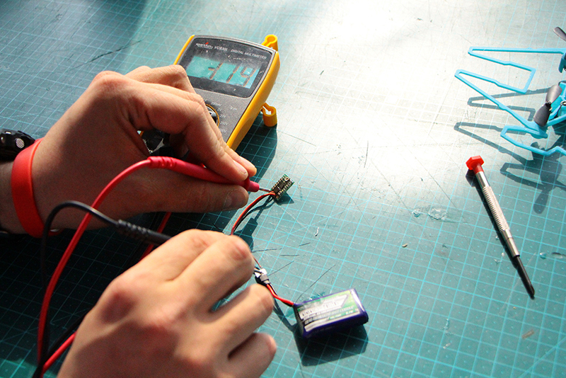
We power the polulu WITHOUT connecting the video equipment! We can do it directly to a fully loaded lipo battery and we measuree the voltage with a multimeter.
BE CAREFULL TO DON'T MAKE ANY SHORT WITH THE MULTIMETER CLAMPS OR YOU WILL INSTANLY KILL THE POLULU.
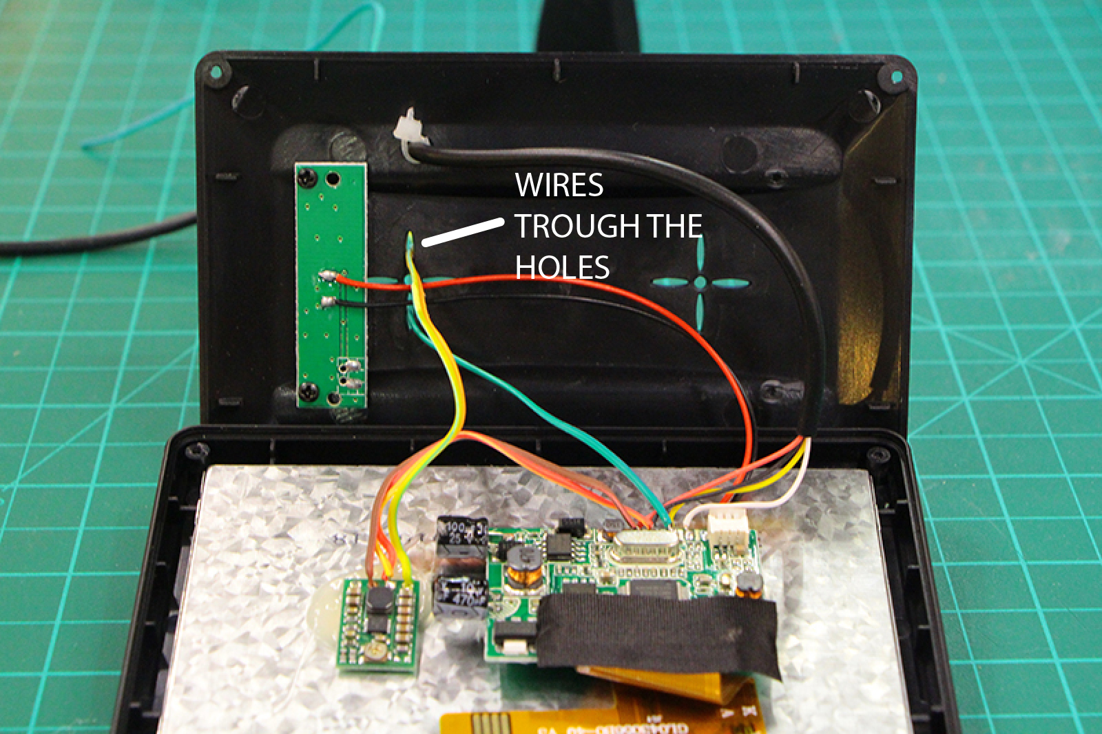
We can start assemblying the components in our frame.
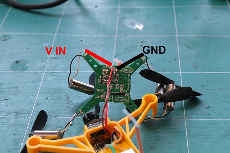
We proceed to solder the wires that come from the polulu to the lipo connecto on the board.
DON'T MISTMATCH THE POLARITY OF THE CONNECTIONS!
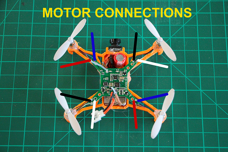
We have two types of motors ones with a blue and a red wire and others with a black and white wire.
BLACK AND WHITE > > > COUNTER CLOCKWISE ROTATION
RED AND BLUE > > > CLOCKWISE ROTATION
06![]()
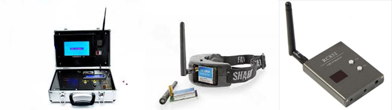
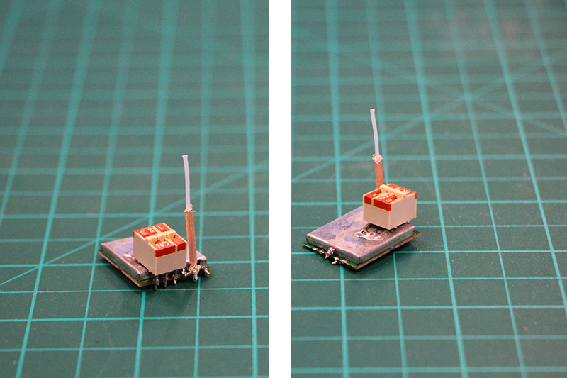
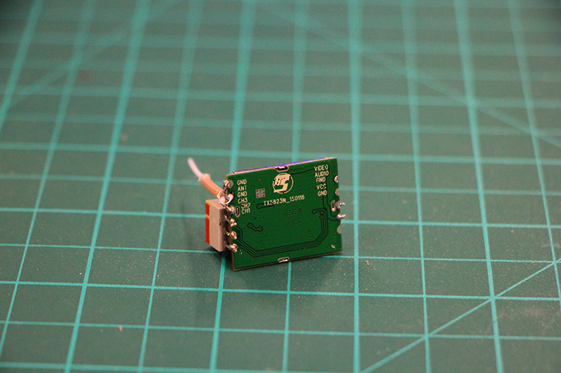
> > > > > > > > Part six - fpv-2 "video receiver"
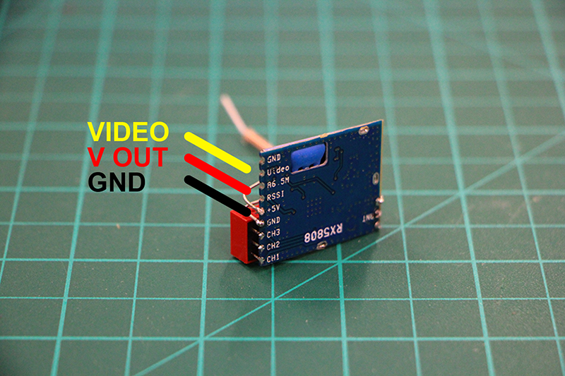
We proceed to assemble the video receiver the process is very similar to the transmitter one.
We will use:
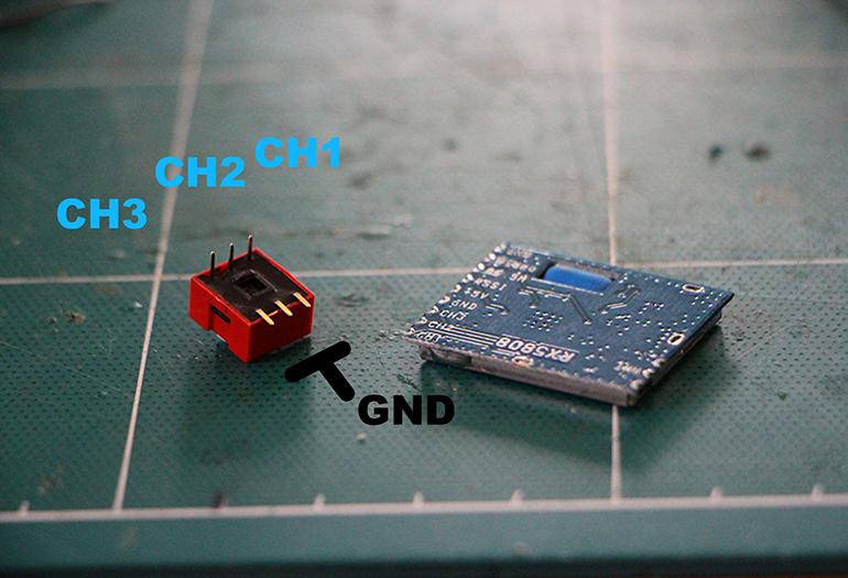
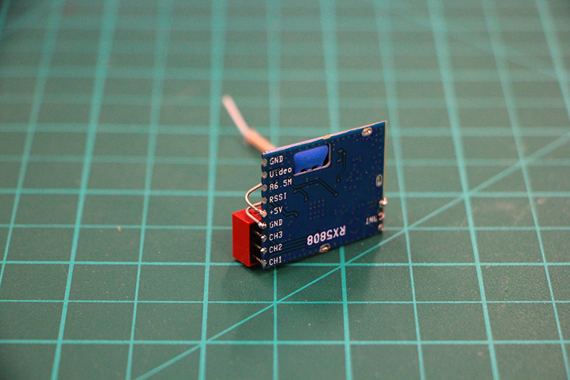
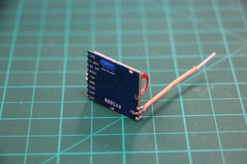
> > > RX5808 5.8ghz receiver
> > > 3 WAY DIP SWITCH
> > > Coaxial wire antenna
> > > 6.3v 1000uf CAPACITOR
Same as we did with the transmitter we make a mini fork with the coaxial wire. Leaving the minimum central wire exposed as possible.
Bend the capacitor wires on an 90"degrees angle to keep it touching the metal shield of the receiver.It should look like this.

07![]()
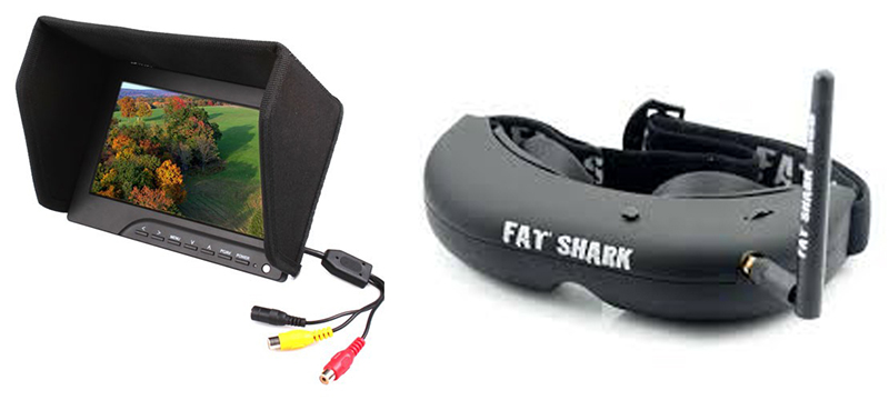
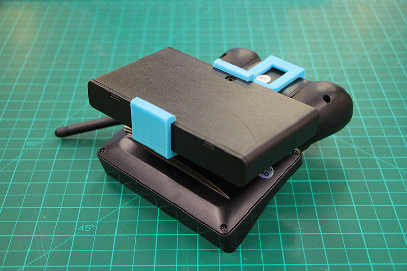
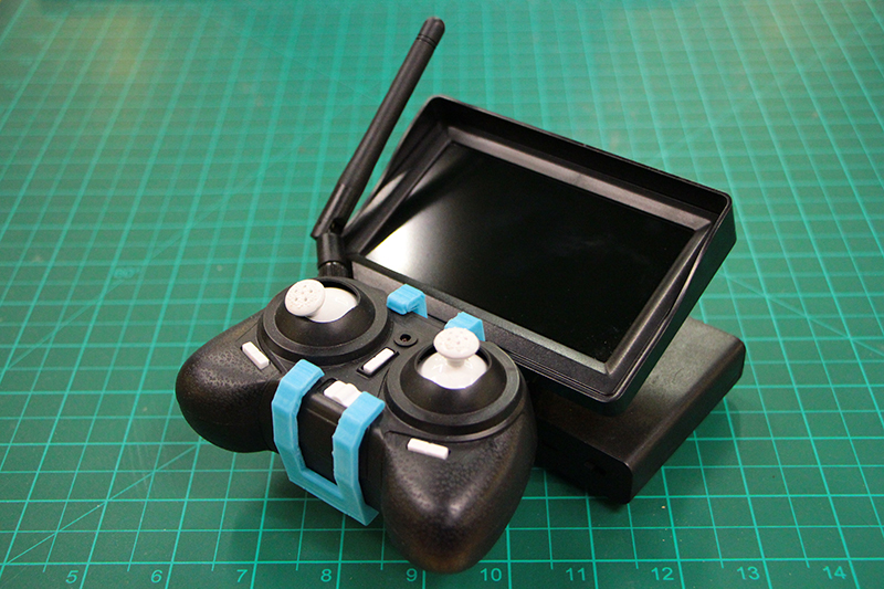
> > > > > > > > Part seven - FPV-3 "Ground Station"
IF YOU WANT TO USE FPV CARBOARD HEADSET YOU CAN SKIP THIS PART UNTIL NEXT CHAPTER.
08![]()
> > > > > > > > Part eight - FPV-4 "Googles mount"
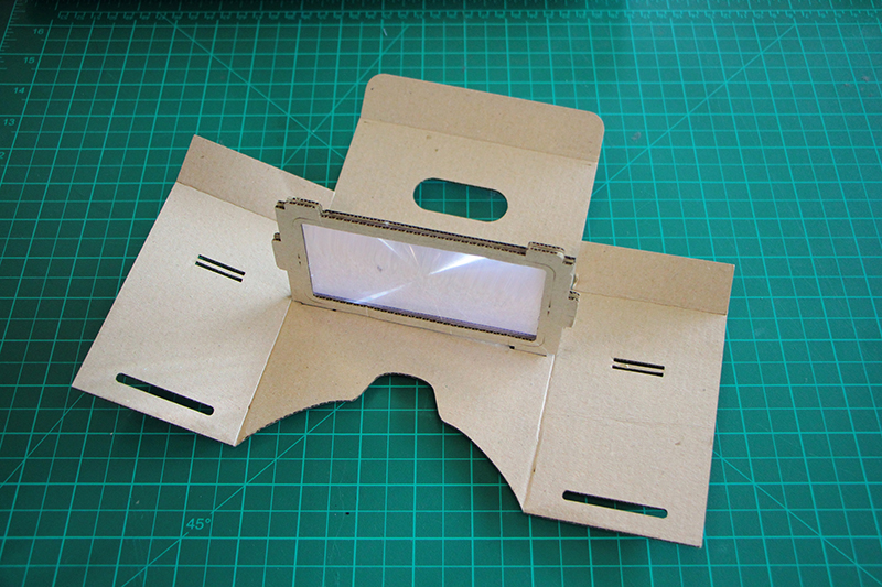
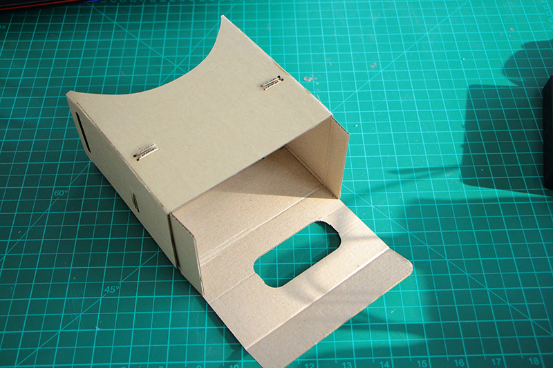
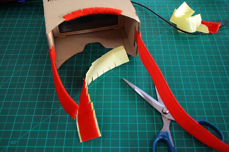
The procedure of the assembling the cardboard googles fpv headset it is quite simple so follow the images for the bending procedure.
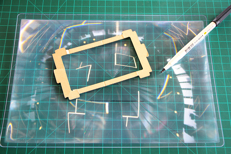
We have to cut the fresnel lens to the size of our lens holder. MARK WITH A PERMANENT MARKER AROUND THE CARBOARD.
NOT INSIDE!!!!
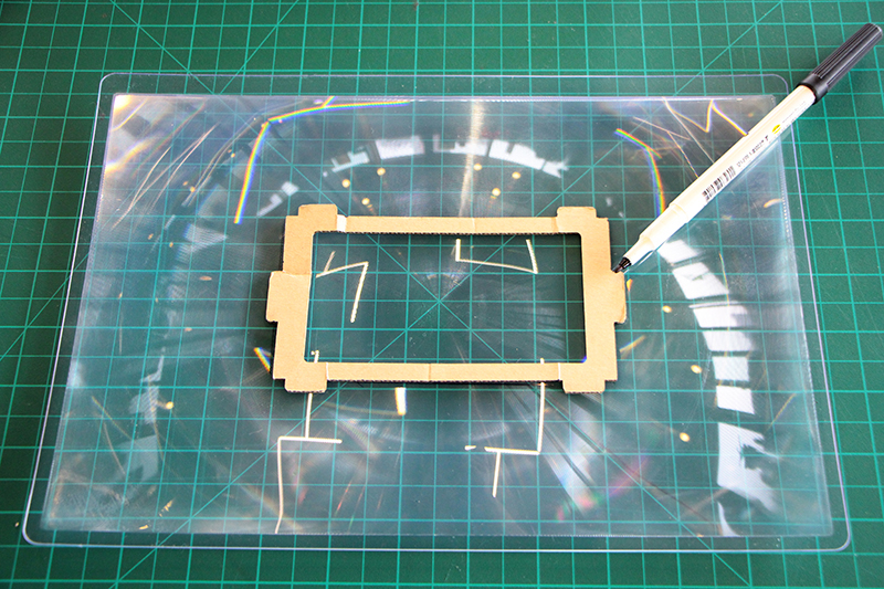
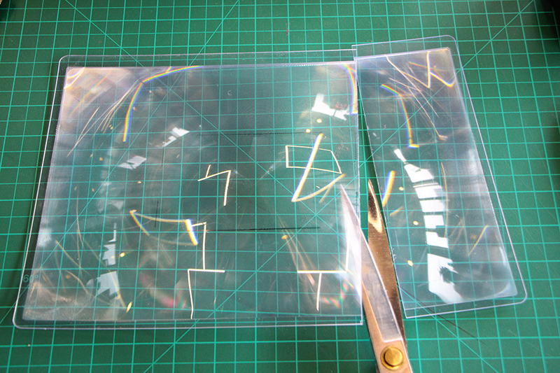
Cut the fresnel lens following the lines with some scissors.Be carefull to don't cut yourself.
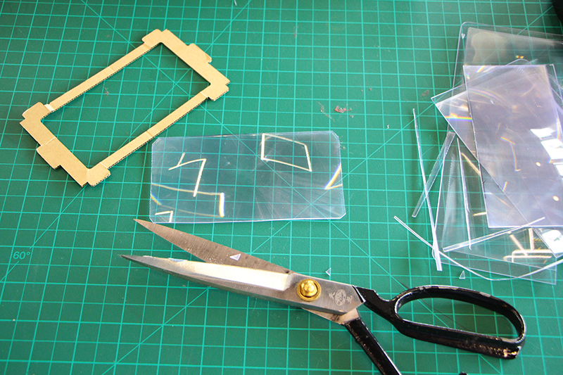
Do some retouch to fit it properly to the size of the carboard. It should be a little bit smaller than it.
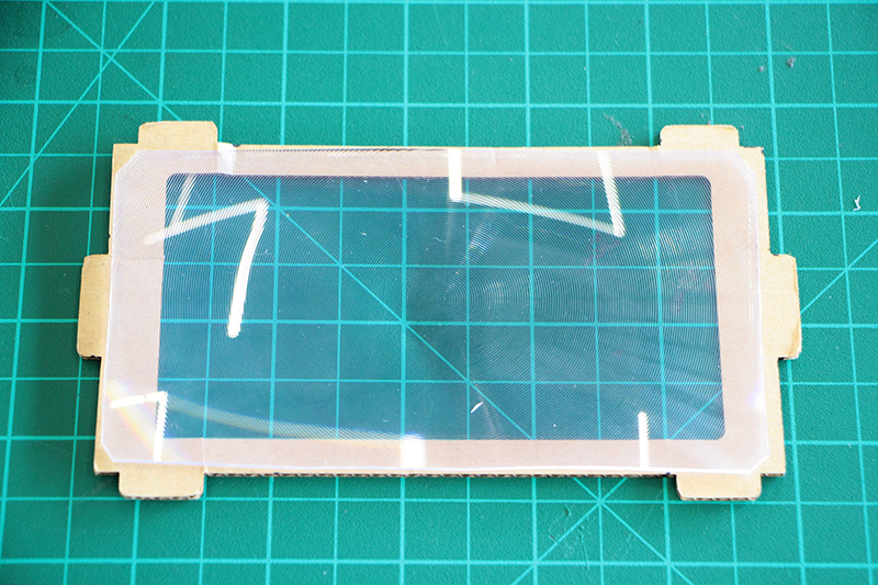
Place a little bit of hot glue in one of each corner to keep it in place.
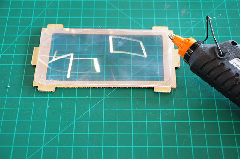
Now do it again to close the "sandwich"
carboard > > > fresnel lens > > > cardboard
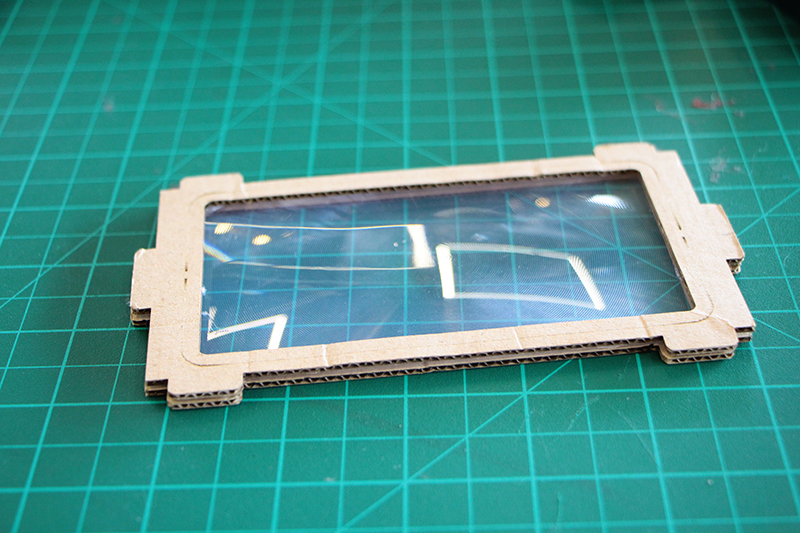
Place the lens in the holes of the down part marked with " inside in of the sides" and bend to the inside.
Just like this.
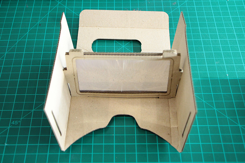
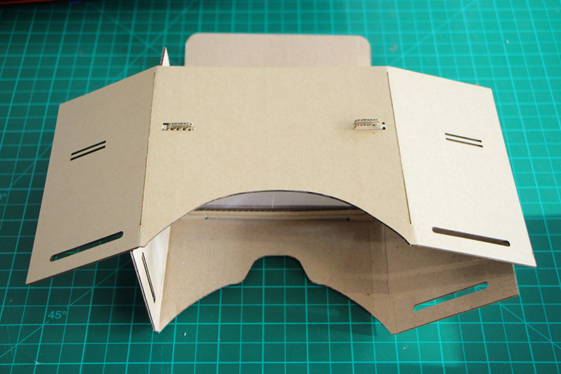
Attach the top and the bottom with double side tape of hot glue.
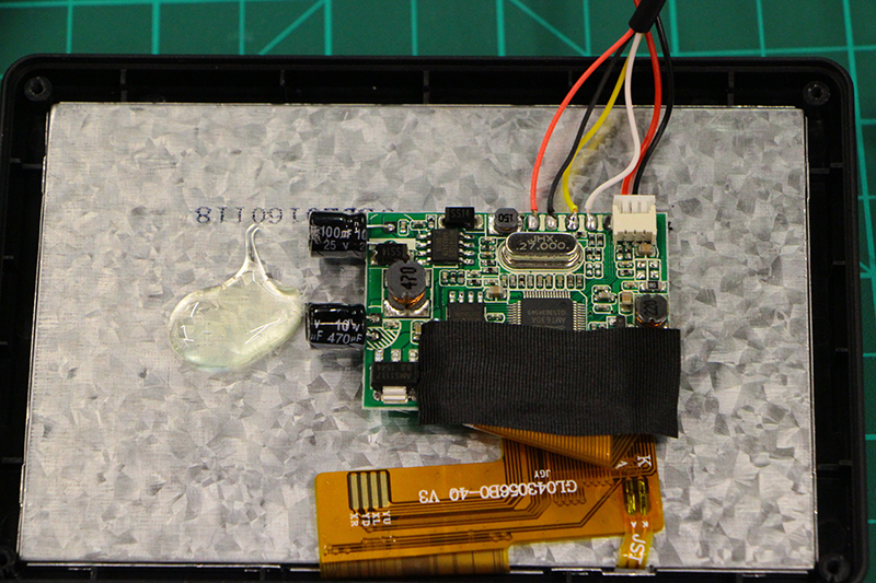
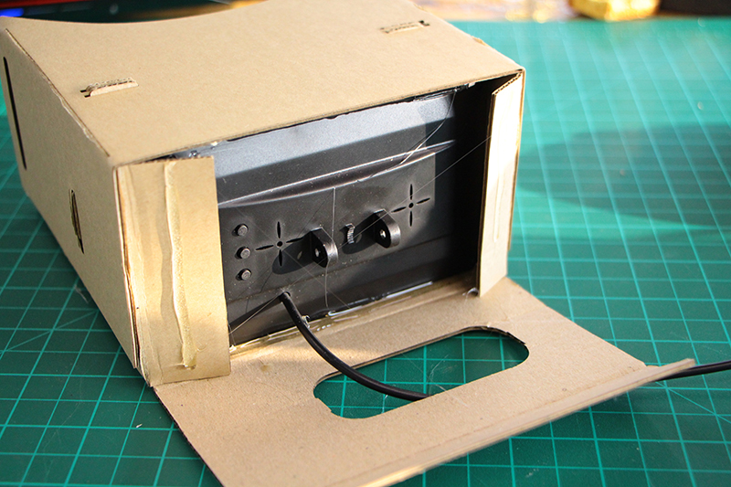
Fit the screen inside one you have FINISH PLACING THE POLULU INSIDE THE SCREEN!
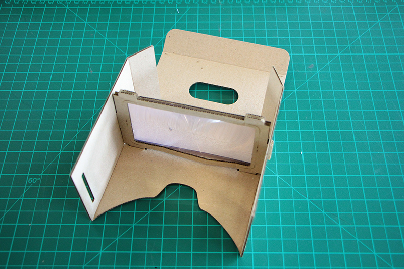
Fix the screen with a little bit of hot glue of double side tape to keep it in place. You should try the focusing distance of the screen for you. For each person it changes a little bit front or back.
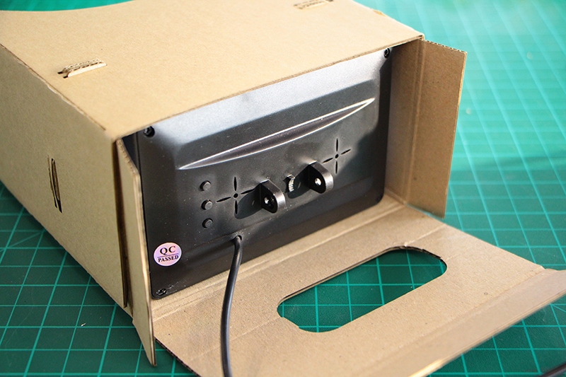
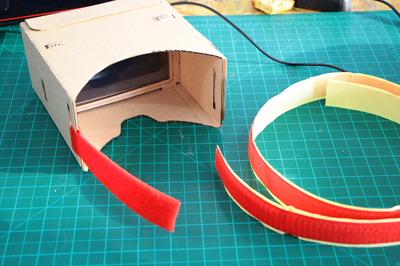
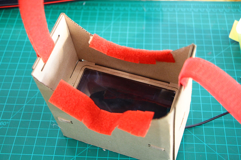
Close the lateral tabs and the big frontal tab. I recommend using velcro/double side tape so you can dissasemble in the future in case you want to take off the screen.
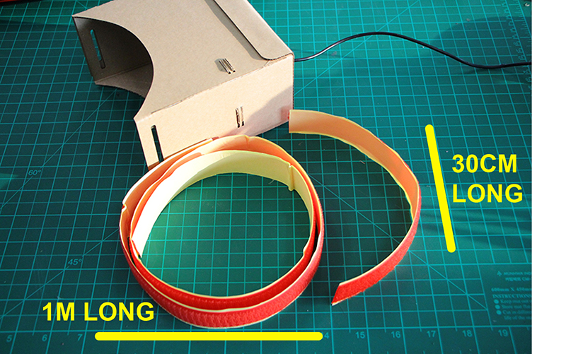
Cut two velcro straps. One of 30 cm long and another of 1meter. Cut one of the smooth type and one of the rough one. NOT BOTH OF THE SAME!
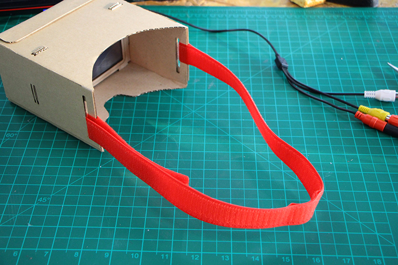
introduce the short part on one side until half and put away the protector film. Gluing both sides together.Do it gently it is very gluing you will have problems to separate the parts if you don't do it well on the first shot.
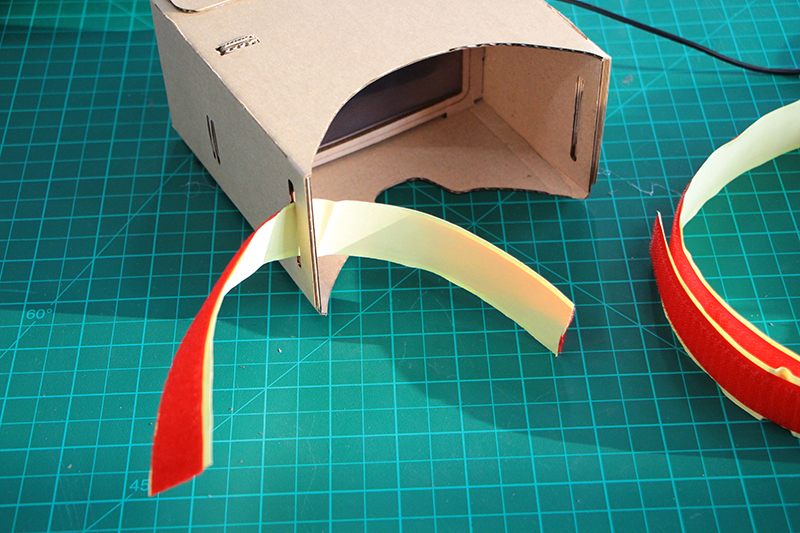
I recommend to start from the end and smoothly put a little bit and glue it on each time, not everything at once.
Once finish proceed to do the same with the longest part on the other side.
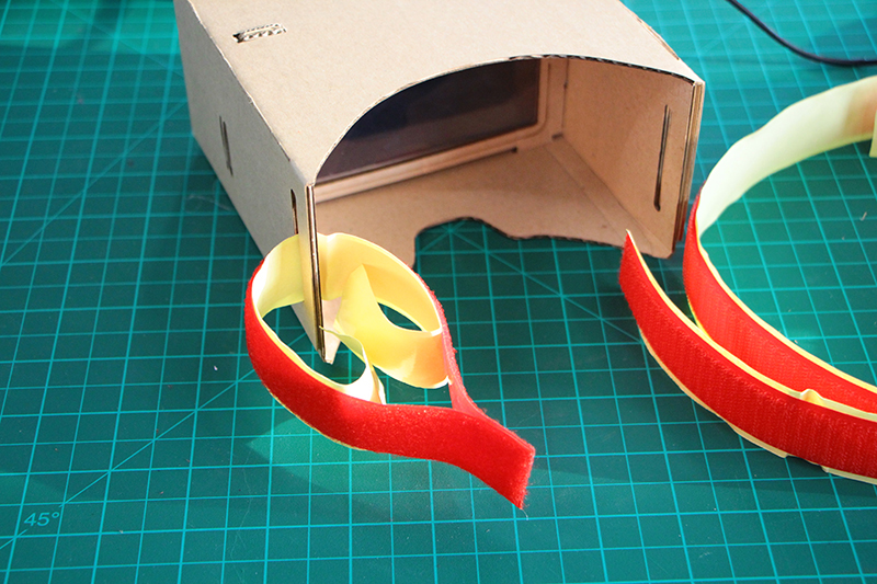
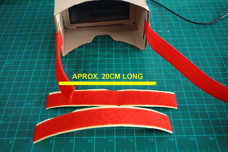
Now we are going to cut two more strippes.Cut the "smooth velcro" ones, more or less 20 cm.These parts are for make the fit to our head more comfortable.
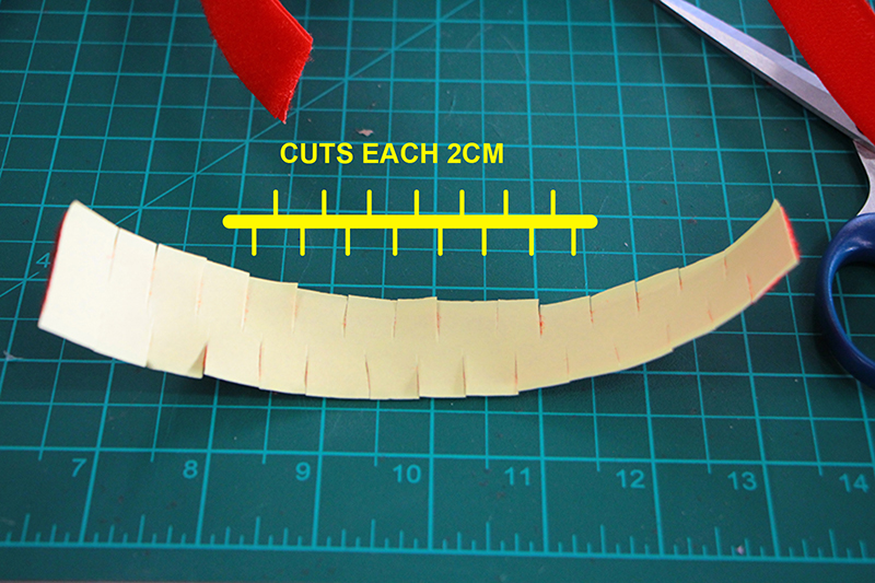
To make it easier to adapt to the round shape of the headset do some cuts on both sides.
And glue it to the front and nose sides.
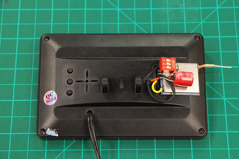
The receiver holder will be screwed with the same screw that comes with the support off the screw, so don't loose it!
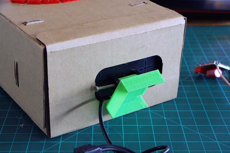
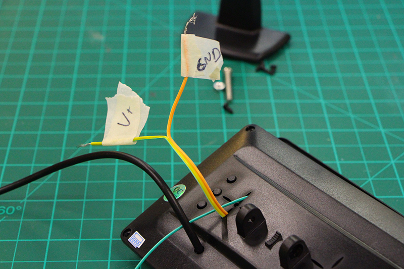
Once place the receiver case proceed to solder the connections to the receiver.
Connect the three wires comming out of the screen to the transmitter. Don't worry if the wires are long.There is enough space in the case to hold everything.
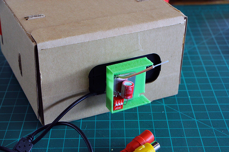
Put a little bit of hot glue on the back of the receiver to keep it in place. The antenna can be a little bit longer and come out of the case. You can bend it until if fits inside of make a tiny hole to keep it out.
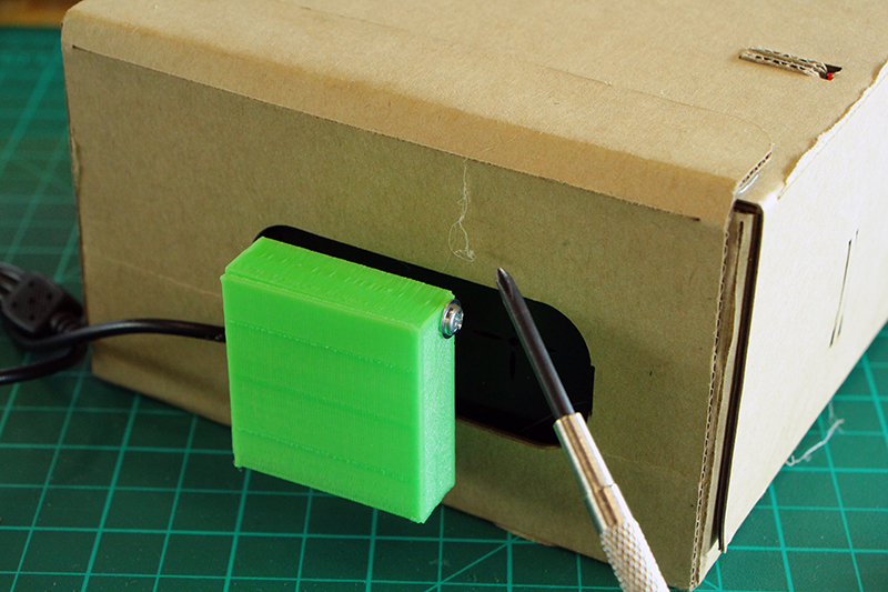
We screw the front part of the case to protect everything from dust/water ,etc
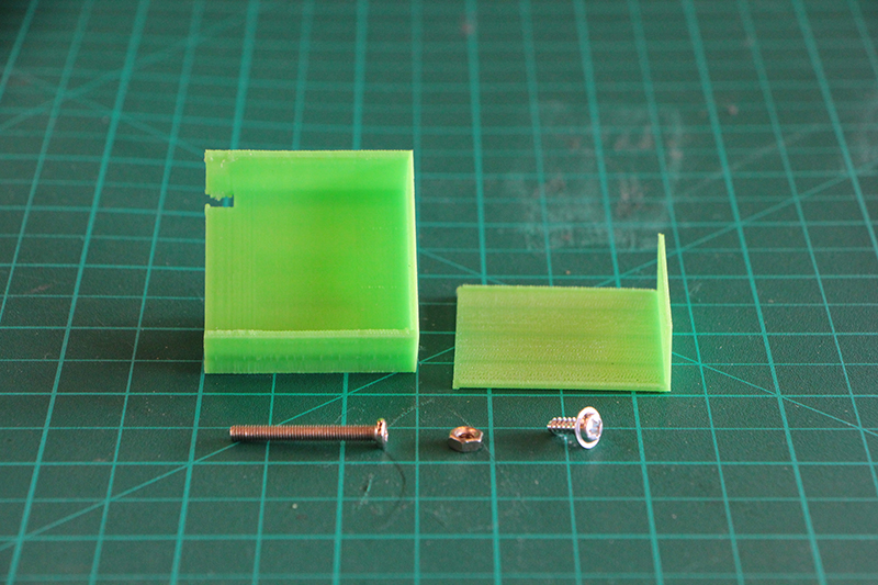
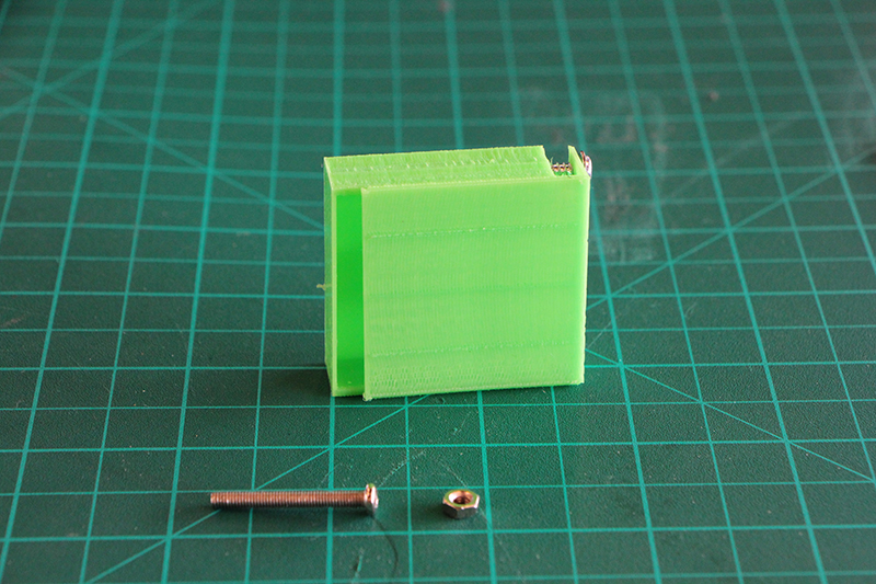
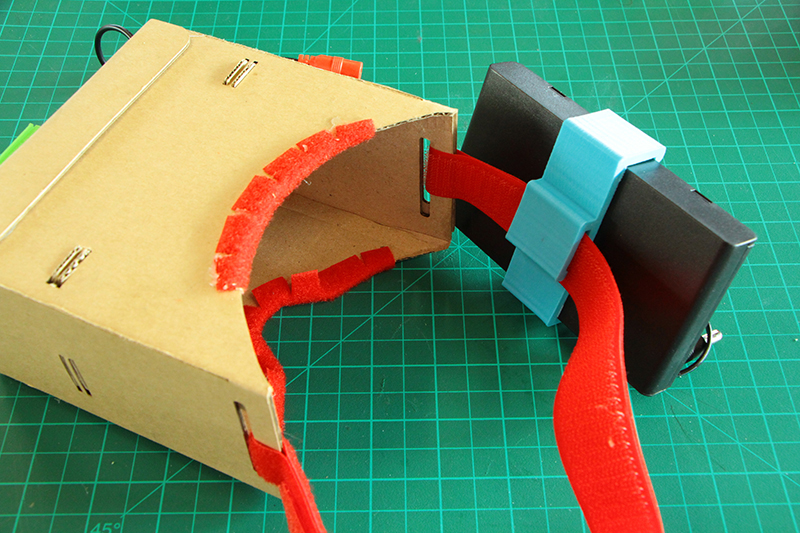
Now it is turn to assemble the battery backpack holder. Put the batteries inside the case before assemblying! It uses 8 AA batteries.
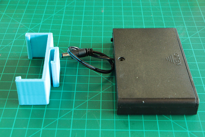
The 3d printed part it is just a clip between the velcro strap and the case. If it moves to much a little bit of hot glue will help.
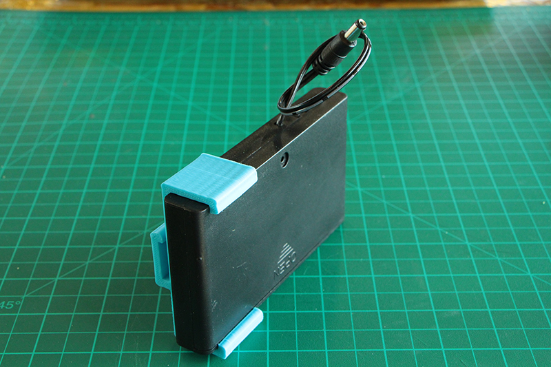
Once finish,clip the holder on the velcro strap. The position doesn't matter ,place it where you feel confortable.
Connect the plug between the battery backpack and the the screen connector and voila.For power on everything there is a switch on the battery backpack.
You should notice you have a red/white/yellow connections leftovers. There are spare AV TV OUT/IN connections for connecting everything to another friend so he can also see everything or to a TV.
09![]()
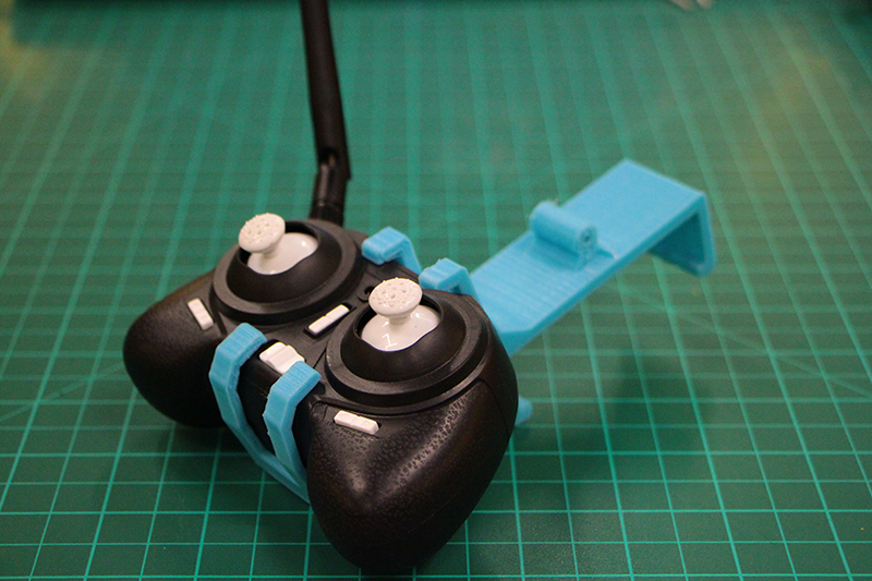
> > > > > > > > Part nine- "Remote hacking"
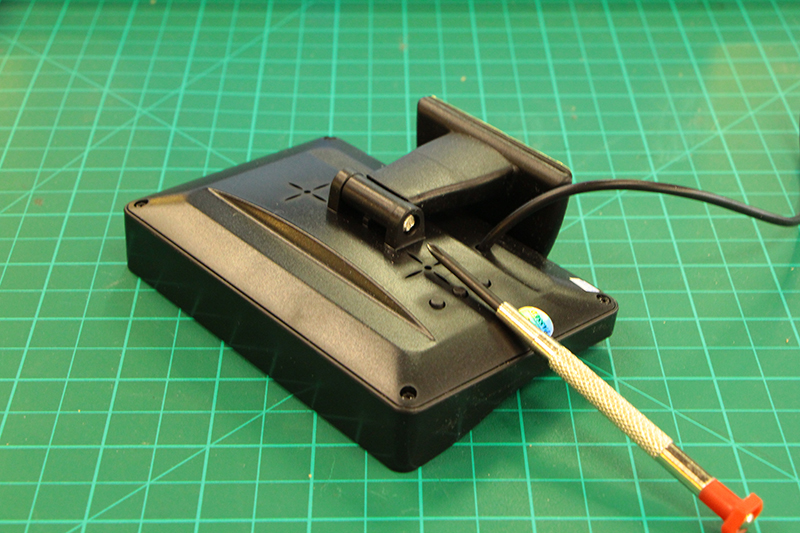
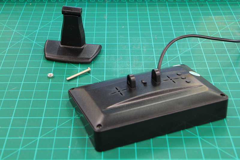
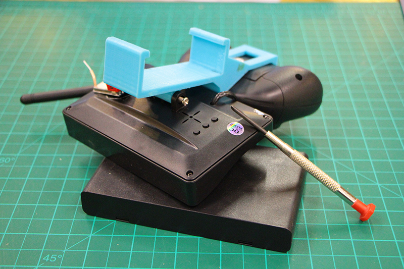
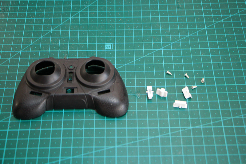
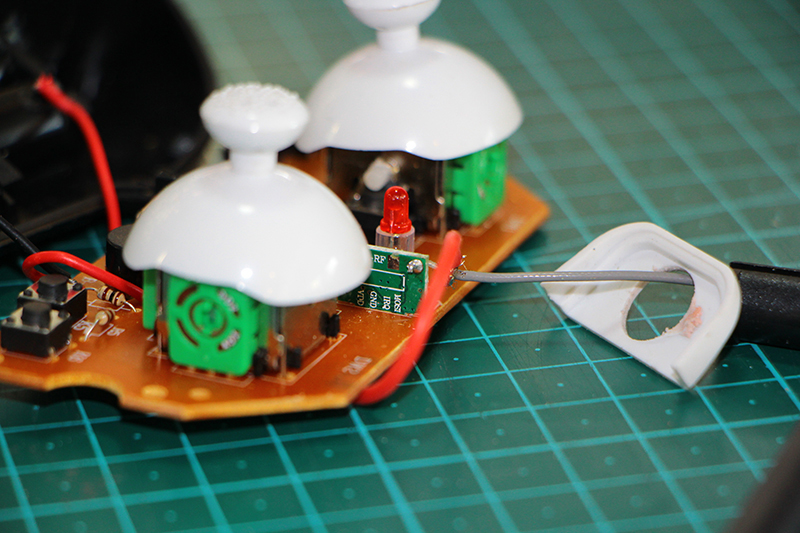
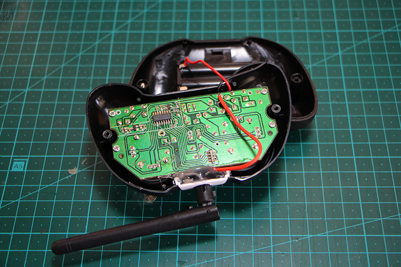
The main range of the remote controller is a little bit short 50-100m for flying Fpv.That is because it's antenna is just a wire soldered directly to the main board. We are goint to disasemble the controller to replace the antenna for a better one with more gain ( sensitivity). We proceed to disasemble it with the screws on the back. Be carefull with the small white button that are just placed in the front.
THIS PART IS NOT STRICTLY NECESSARY, DO IT ONLY IF YOU FEEL CONFIDENT WITH THE SOLDERING IRON. THE SOLDERINGS ARE EXTREMELY DIFFICULT.
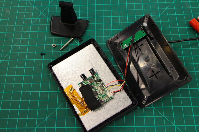
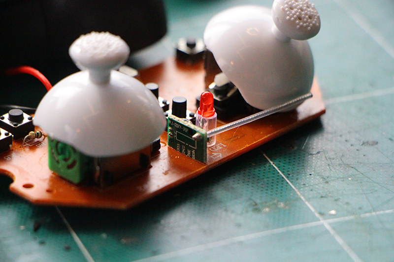
This is the wire antenna that we have to replace. As you see it is the most difficult part of the whole workshop as the space for soldering and the soldering pads are very small.
Proceed to heat the back on the wire with the soldering iron to take it away.
With the coaxial antenna wire. Peel it off to leave the main antenna (central wire) discovered and tight all the antenna shield on the side ( ground connection)
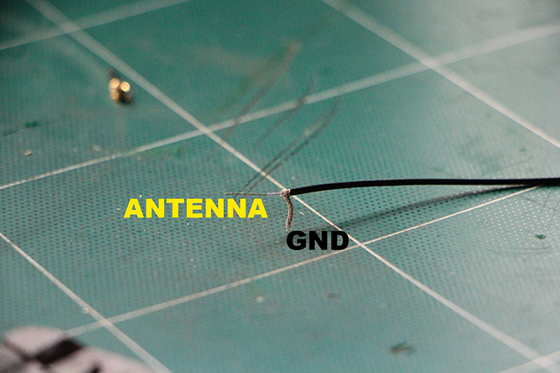
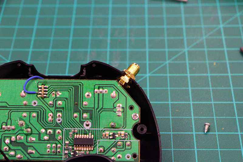
Solder the central part of the new antenna where the old antenna was. Try to leave the less amount of "unshielded" antenna.As it may decrease the range.
Proceed to solder another wire to the shield part of the coaxial wire. We are going to connect this new wire to a ground pad on the back of the transmitter board.
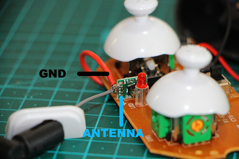
We have several GND pads where to connect but these two are the easiest ones.
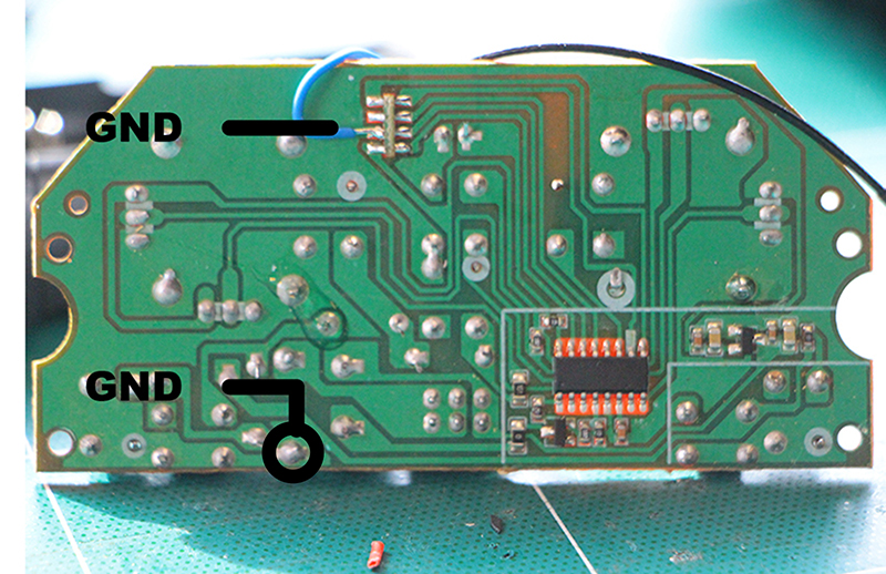
It should look like this. WOOAH!
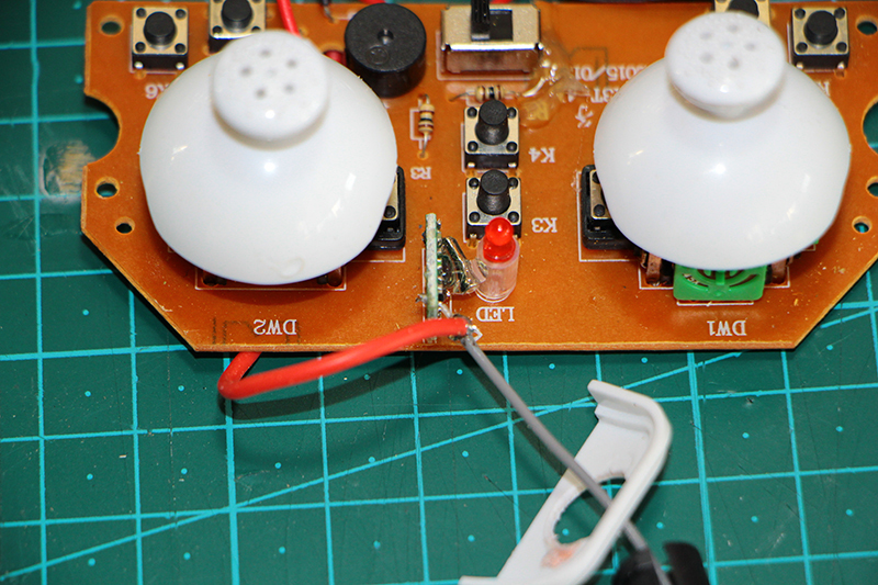
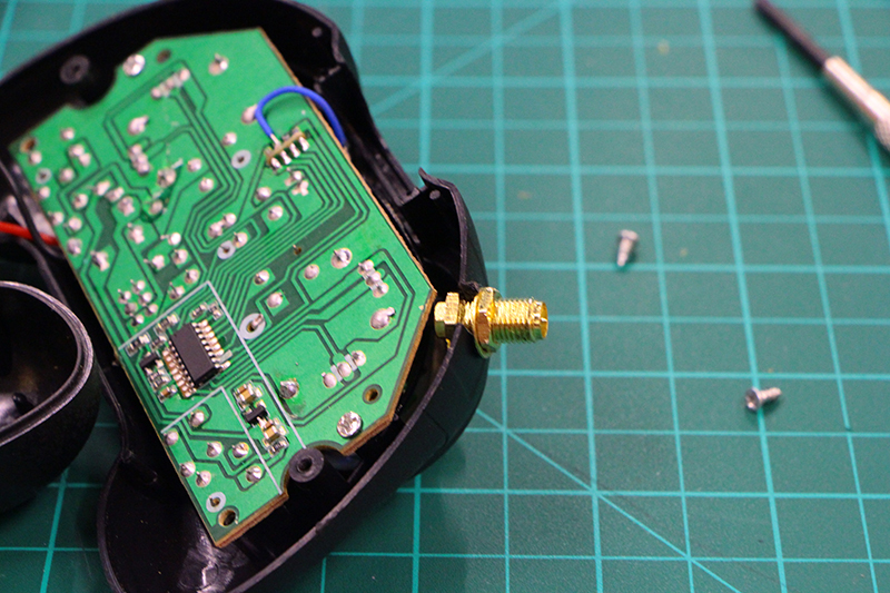
Another view
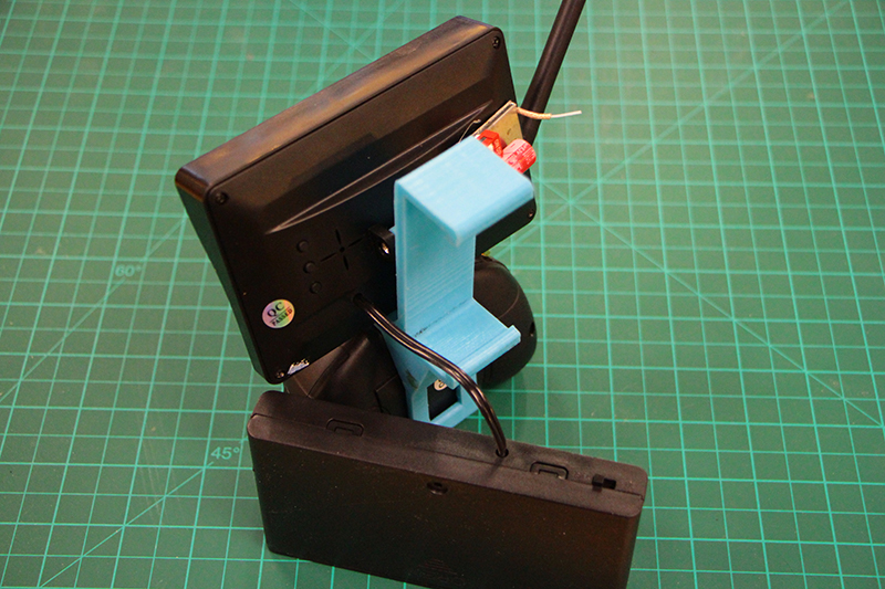
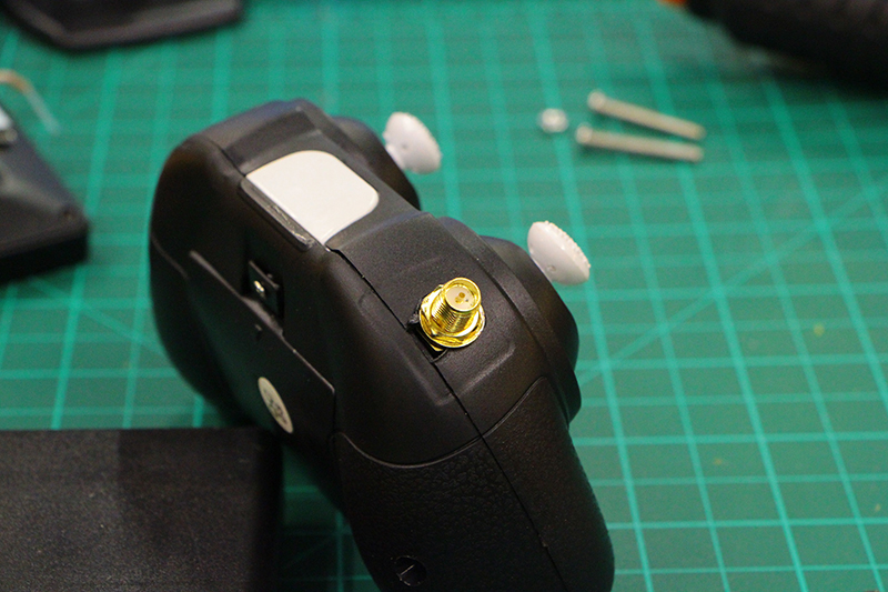
We can make the hole for the antenna connector wherever we want but i really recommend this position. Make a little hole with a "dremel" or just melt the plastic with the solder iron.
Before making any hole check that it will not interfere with the josticks movement or while reassembling the remote.
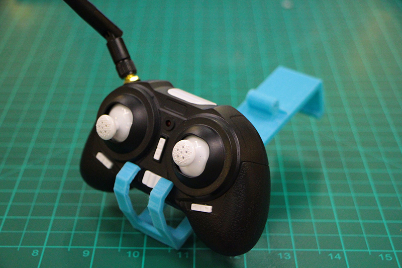
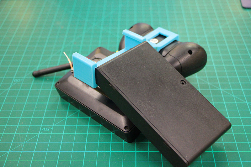
We reassemble the remote all together. Making a hole on the frame on the positiion where we want to have the new antenna connection.
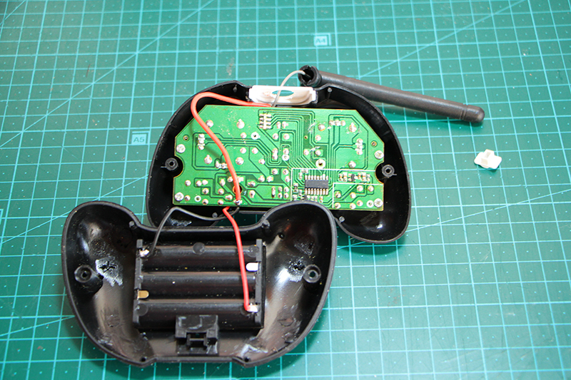
Tigtht the antenna connection with the bolt and washer.
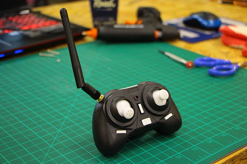
Attach the antenna gently by turning clockwise and ready to control. Don't forget to put the batteries on the remote. It uses 3 AAA batteries.
10![]()
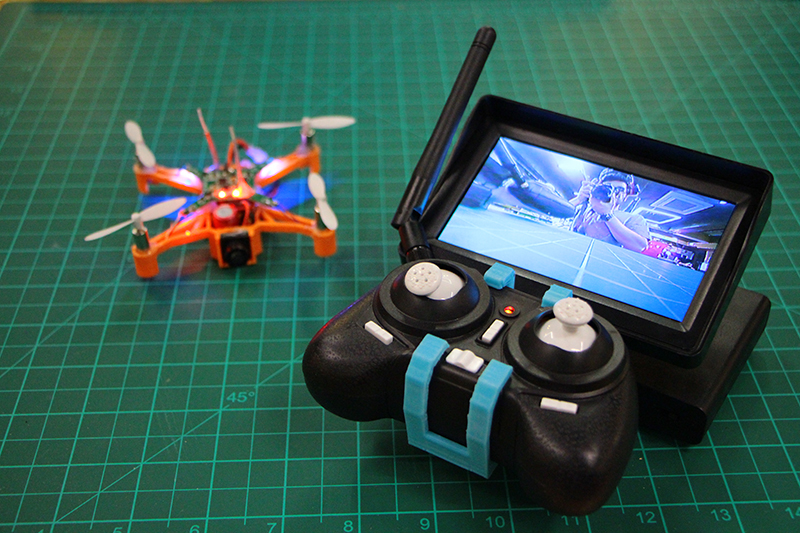
> > > > > > > > Let's fly! TIPS AND TRICKS
NOW IT IS TIME TO FLY!
Before flying check that all the propellers turn in the correct position and are correctly located. There is two types clockwise and counterclockwise.
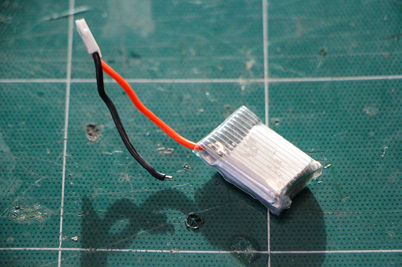
Connect first you lipo battery to the BeanDrone.
Switch on your remote controller and push up and down your left throttle stick to bind to your drone.
Switch on the battery backpack to power on your tv screen and receiver.
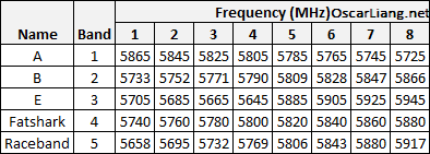
If you don't see any image on your headset/screen check that you are using the same transmission/receiver channel on the transmitter/receiver.
You can select different channels by sliding up and down the switches.
Receiver channels
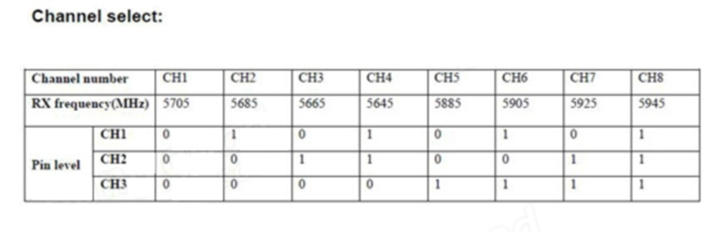
Transmitter channels
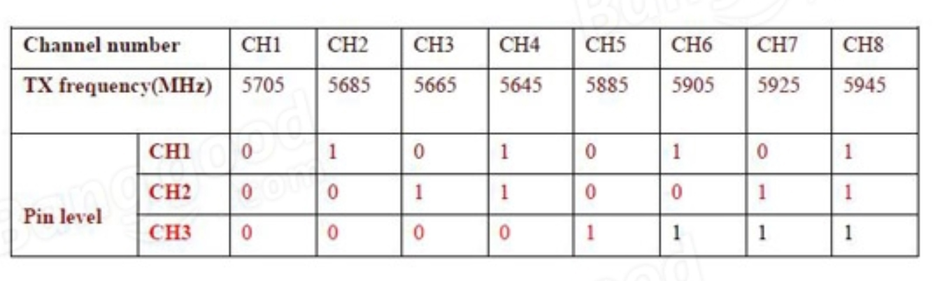
For example if i want to use CH1 all the switches on both transmitter and receiver are "down"
TIPS AND TRICKS
> > > Depth Perception trough your new eyes
One of the hardest things to get used to when flying FPV is the height and depth of the surrounding elements now that you are starting through a security camera.
Fly around something you know well how it look alike and which size you know until you get “used to” what it looks and feels like and how it is to be 3 meters above the ground.
> > > Use a spotter
When you first start flying FPV, you need to remember that you can’t see anything around you or your quad. If you’re at the park – you might not see the small children entering the park from an entrance behind you until it is too late. Bring a friend to help you while starting to fly so he can tell you if you are to close to something.
> > >No reverse
You can’t see anything behind yourself.Suck it up cupcake.
> > >Start small
If possible, fly with experienced friends so you can “buddybox” for interactive feedback.
Don't try to race and experience high speed on the first try.
Just try to keep you quadcopter under control and know where you are.
> > > Things are fragile
Be carefull while taking off the battery of the drone don't stress to much the battery wires of you will break them.
Quadcopters breaks if you crash to much so learn to fix it!
![]()
> > > > > > > >EXTRA-EXTRA > > > KIT PARTS
If you have reached this point it means you have make your kit and you want to make another one or unluckly you crashed to much and need replacements.
So here is the list of all the components and some internet links.
> > > 2.4GHz 3dBi RP-SMA Connector Booster Wireless Antenna
> > > 12V 8 x AA Battery Holder Case Box
> > >10cm PCI U.FL / IPX to RP-SMA Female Jack Pigtail Cable
> > > 5.8G 200mW Wireless Audio Video Transmitter Module TX5823
> > > 5.8G Wireless Audio Video Receiving Module RX5808
> > > 600TVL 1/4 1.8mm CMOS FPV 170 Degree Wide Angle Lens Camera
> > > RF Coaxial RG178 10 Feet
> > > Receiver Board H8mini-004
All the contents are created by Eduardo Chamorro and are licensed under a Creative Commons Attribution-NonCommercial-ShareAlike 4.0 International License.